Iron-chip removing machine

A technology for removing iron pins and racks, which is applied in filing/filing devices, filing/filing devices, metal processing equipment, etc. It can solve the problems of easily scratching the operator, labor and time, and achieves a simple structure Effect

Inactive Publication Date: 2015-11-18
苏州金牛精密机械有限公司
View PDF6 Cites 3 Cited by
  • Summary
  • Abstract
  • Description
  • Claims
  • Application Information

AI Technical Summary

Problems solved by technology

[0002] Due to the production process, metal workpieces often have iron pins and burrs after production. Therefore, iron pins and burrs often need to be rem...

Method used


Image

  • Iron-chip removing machine
  • Iron-chip removing machine

Examples


Embodiment Construction

[0014] The present invention will be further described below in conjunction with the accompanying drawings. The following examples are only used to illustrate the technical solution of the present invention more clearly, but not to limit the protection scope of the present invention.

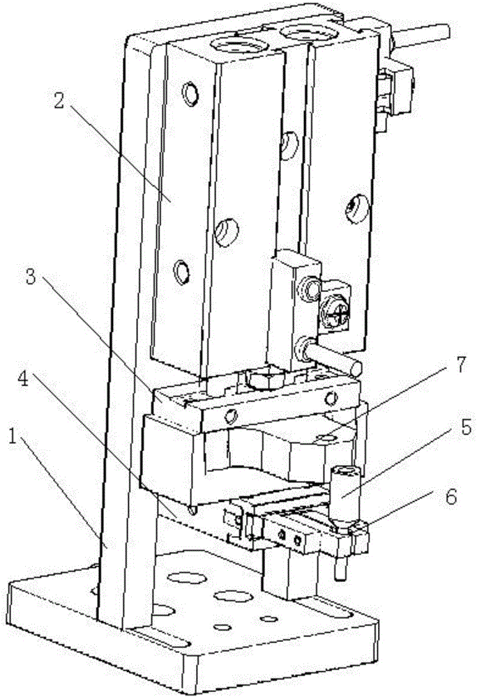
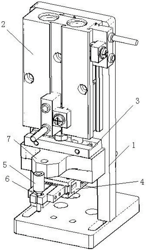
[0015] Such as figure 1 and 2 The shown iron pin removal machine includes a frame 1, a punching machine 2 is installed on the upper part of the frame 1, the upper part of the punching machine 2 is a movement, and the lower part is a punch 3, and the lower part of the punching machine 2 is installed Clamp 4 is arranged, and the head of described clamp 4 has a fixing hole 6 for placing workpiece 5, and metal block 7 protruding to the side is installed on described punch 3, and described metal block 7 is positioned at described Directly above the clamp 4 , when the punch 3 is pressed down, the raised surface of the metal block 7 is in close contact with the side surface of the workpiece 5 .

[0...


PUM


Abstract

The invention provides an iron-chip removing machine. The iron-chip removing machine comprises a machine frame. A punching machine is mounted on the upper portion of the machine frame. A machine core is arranged on the upper portion of the punching machine, and a punch is arranged on the lower portion of the punching machine. A clamp is mounted below the punching machine. A fixing hole used for containing a workpiece is formed in the head of the clamp. A metal block protruding towards a side face is mounted on the punch. The metal block is located over the clamp. After the punch is pressed downwards, the side face of the metal block is tightly attached to the side face of the workpiece. The iron-chip removing machine is used for removing iron chips on the specific portion of the workpiece in a mechanical punching mode, and is simple in structure, high in efficiency and suitable for polishing the metal workpiece.

Description

technical field [0001] The invention relates to an iron pin removing machine, which belongs to the field of manufacturing equipment. Background technique [0002] Due to the production process, metal workpieces often have iron pins and burrs after production. Therefore, iron pins and burrs often need to be removed after production. The common method is manual grinding, but manual grinding is often laborious and time-consuming. , and it is easy to scratch the operator. Contents of the invention [0003] The technical problem to be solved by the present invention is to provide a mechanism with simple structure, high efficiency and capable of mechanically removing iron pins. [0004] In order to solve the above problems, the technical solution of the present invention is: an iron pin removal machine, including a frame, a punching machine is installed on the upper part of the frame, the upper part of the punching machine is a core, the lower part is a punch, and the punching ...

Claims


Application Information

Patent Timeline
IPC IPC(8): B23D67/02
Inventor 周建荣
Owner 苏州金牛精密机械有限公司
Why Eureka
Try Eureka