Error compensating method for material-increase manufacturing

A technology of additive manufacturing and error compensation, which is applied in the field of additive manufacturing, can solve the problems of large Z-direction dimensional error, deformation, and inability to deal with Z-direction penetration errors, etc., and achieve the effect of improving precision and forming quality and reducing dimensional errors

Active Publication Date: 2015-11-18
TSINGHUA UNIV
View PDF5 Cites 19 Cited by
  • Summary
  • Abstract
  • Description
  • Claims
  • Application Information

AI Technical Summary

Problems solved by technology

[0014] The above-mentioned error compensation method, because the minimum deposition unit has the characteristics of three-dimensional XYZ three-dimensional unequal dimensions, and the existing compensation cannot deal with the Z-direction penetration error, resulting in a large Z-direction dimensional error of the part, resulting in deformation; at the same time, because the minimum deposition The size of the unit in the XYZ direction is differe

Method used


Image

  • Error compensating method for material-increase manufacturing
  • Error compensating method for material-increase manufacturing
  • Error compensating method for material-increase manufacturing

Examples


Embodiment 1

[0101] There are many ways of additive manufacturing, a typical way is binder jet additive manufacturing.

[0102] For ease of understanding, in this embodiment, the error compensation method for additive manufacturing in the above embodiments of the present invention is further described by taking the binder jet additive manufacturing method as an example.

[0103] In this embodiment, the penetration error compensation method for binder jet additive manufacturing specifically includes the following steps:

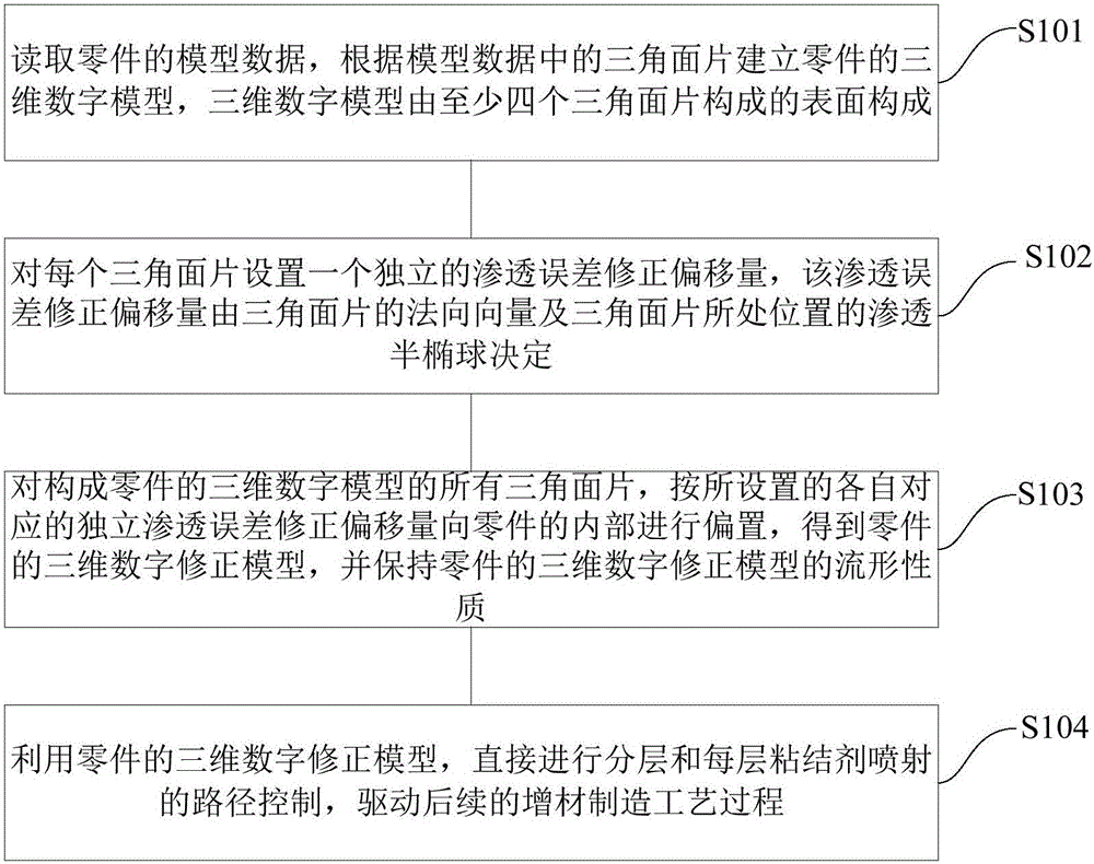
[0104] Step a: read the model data of the part, and establish a three-dimensional digital model of the part according to the triangular faces in the model data, and the three-dimensional digital model is composed of surfaces composed of at least four triangular faces. Among them, the three-dimensional digital model of the part has the topological relationship of point-line, point-plane and line-plane.

[0105] Step b: Set an independent penetration error correction offset...

Embodiment 2

[0110] In this embodiment, taking the error compensation method of binder jet additive manufacturing as an example, the specific operation process is as follows:

[0111] 1 Equipment: Binder jet additive manufacturing equipment and other necessary parts. In this example, the PCM technology developed by the Mechanical Engineering Department of Tsinghua University is selected.

[0112] 2 data: the sample triangular patch model, which is a cube model, for example Figure 10 (a) and Figure 10 (b) shown.

[0113] 3. Purpose of the experiment: To compensate the penetration error of the sample model by using the compensation method of the penetration error based on the triangular patch model.

[0114] 4 Implementation steps:

[0115] A: Reconstruct the topological relationship of the sample triangular mesh model data, and repair the topological errors to generate a 3D mesh model.

[0116] B: According to the theoretical seepage model, perform theoretical seepage error compensati...


PUM


Abstract

The invention provides an error compensating method for material-increase manufacturing. The method includes the steps that model data of a part are read, and a three-dimensional digital model of the part is established according to triangular face sheets; an independent correction offset is set for each triangular face sheet and determined by a normal vector of the triangular face sheet and the semi-ellipsoidal shape of a sedimentation unit at the position where the triangular face sheet is located; all the triangular face sheets forming the three-dimensional digital model of the part are deflected to the interior of the part according to the set independent correction offsets corresponding to the triangular face sheets, a three-dimensional digital correction model of the part is obtained, and the manifold property of the three-dimensional digital correction model of the part is maintained; and layering and material-increase manufacturing of each layer are directly performed to achieve path control of a sedimentation path according to the three-dimensional digital correction model of the part, and a subsequent material-increase manufacturing craft process is driven. The error compensating method can reduce anisotropy forming errors caused by anisotropy of the size of the sedimentation unit during material-increase manufacturing and increase material-increase manufacturing precision and forming quality.

Description

technical field [0001] The invention relates to the technical field of additive manufacturing, in particular to an error compensation method for additive manufacturing. Background technique [0002] The core of additive manufacturing technology is the idea of ​​discrete stacking. Its principle is to slice the 3D model of the part to obtain a series of parallel two-dimensional plane profiles, and then superimpose and deposit each layer through the manufacturing equipment to obtain the final part. Additive manufacturing is a new type of forming method, which differs from the traditional removal process and adopts the method of gradually accumulating materials to manufacture three-dimensional entities. It is a "bottom-up" manufacturing method, which is directly driven by the three-dimensional data of the parts and manufactured in layers. Rapid prototyping (RAPID PROTOTYPING, RP), physical freedom manufacturing, 3D printing, etc. are different names for this type of technology. ...

Claims


Application Information

Patent Timeline
IPC IPC(8): B29C67/00B33Y50/02
Inventor 林峰马旭龙张磊
Owner TSINGHUA UNIV
Why Eureka
Try Eureka