
A Track Broken Monitoring System for Intervals

A monitoring system and interval technology, applied in the field of rail transit, can solve the problems of inability to use seamless line monitoring, inability to monitor the complete state of rails in real time, inability to detect rail breaks and their fault locations, etc.

Active Publication Date: 2016-09-21
SHANGHAI TIEDA ELECTRONICS & INFORMATION TECH CO LTD
View PDF4 Cites 0 Cited by
  • Summary
  • Abstract
  • Description
  • Claims
  • Application Information

AI Technical Summary

Problems solved by technology

For example: "Method and equipment for determining the location of broken rail" and "broken rail monitor" proposed by German Lorenz Standard Electric Company, "rail breakage detection system" developed by American General Signal Corporation, designed by Americans Pete and Orr "Railway signaling system for rail breakage detection", they all need to clean the track bed, and need to set up mechanical insulation in the monitoring area, which cannot be used for the monitoring of seamless lines
[0004] The "Long Rail Breakage Supervision System" developed by the Jinzhou Branch in China mainly acts as a long track circuit and section block. It cannot detect the dynamic breaking of the rail and its fault location; the "AJ-P type Broken rail inspector", which is actually similar to the inspection method of ultrasonic flaw detection, it cannot monitor the complete state of the rail in real time

Method used


Image

  • A Track Broken Monitoring System for Intervals
  • A Track Broken Monitoring System for Intervals
  • A Track Broken Monitoring System for Intervals

Examples


Embodiment Construction

[0050] The present invention will be further described below in conjunction with accompanying drawing.

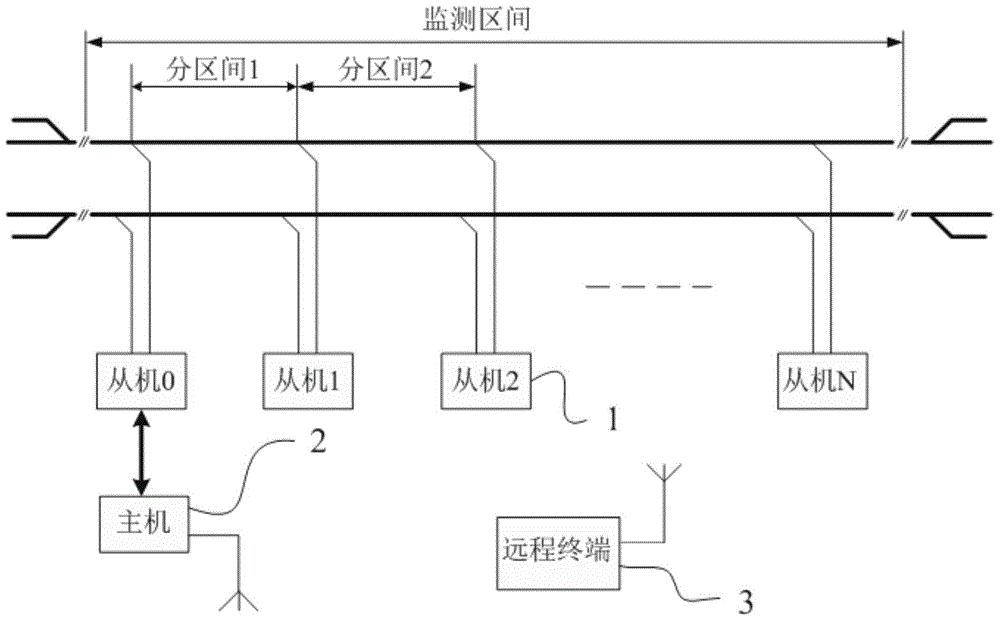
[0051] see figure 1 , divide the monitoring interval into rails in each interval. The section rail broken monitoring system of the present invention includes: a plurality of slave machines 1 correspondingly connected to the rails in each section, a host 2 and a remote terminal 3 wirelessly connected to the host 2 . The slave machines 1 are connected through steel rails to realize step-by-step power carrier communication loaded on the steel rails. Master 2 is connected to a slave 1 via a cable.

[0052] Each slave machine 1 collects its own slave machine status information and the rail status information of the rails in each section, relays and transmits them in the form of power carrier, and finally transmits them to the host machine 2 . A timing synchronization mechanism is introduced between the slaves 1, that is, at the same time, only one slave 1 sends information, a...


PUM


Abstract

The invention discloses a section broken rail monitoring system. The section broken rail monitoring system comprises a plurality of slave machines, a master machine and a remote terminal, wherein the plurality of slave machines are correspondingly connected with section steel rails; the remote terminal is wirelessly connected with the master machine; the slave machines are communicated with each other through steel rails so as to realize communications of step-by-step power carriers loaded on the steel rails; the master machine is connected with one of the slave machines; each slave machine is used for collecting its own slave machine state information and steel rail state information of each section steel rail, transmitting the slave machine state information and the steel rail state information in the form of power carriers step by step and finally transmitting the slave machine state information and the steel rail state information to the master machine; and the master machine is used for analyzing, processing and judging the steel rail state information and the slave machine state information and transmitting obtained results to the remote terminal in a wireless way. According to the section broken rail monitoring system disclosed by the invention, through remote step-by-step transmission of carrier signals on the steel rails, the integrity of the steel rails is monitored in real time, the section of the breakage fault of the steel rail is automatically judged and alarmed, and the section steel rails are remotely and intensively monitored.

Description

technical field [0001] The invention relates to the field of rail transit, in particular to a system for monitoring broken rails in sections. Background technique [0002] In order to implement the railway leap-forward development strategy, the whole railway has achieved the sixth major speed increase. As the speed of the train increases and the tonnage increases, the impact force on the rail and joint welding will increase significantly. Double the size, it is easy to cause cracking and breaking due to stress concentration, thus endangering driving safety. [0003] At present, the real-time monitoring of rail breaking in foreign countries is based on the track circuit, and the input resistance and ballast resistance are tracked and captured to achieve the purpose of detecting broken rails and determining fault points. For example: "Method and equipment for determining the location of broken rail" and "broken rail monitor" proposed by German Lorenz Standard Electric Compan...

Claims


Application Information

Patent Timeline
Patent Type & Authority Patents(China)
IPC IPC(8): B61L23/04
Inventor 祁新陈锦山周道青杨云国张晓华谢竑
Owner SHANGHAI TIEDA ELECTRONICS & INFORMATION TECH CO LTD
Learn More