Self-locking weaving-shaft transport vehicle special for spinning

A transporter, self-locking technology, applied in the direction of lifting device, can solve the problems of high handling intensity, difficult to transport weaving shaft, poor safety, etc., and achieve the effect of improving transportation safety.

Active Publication Date: 2015-11-18
安徽泰阳织造科技有限公司
View PDF4 Cites 1 Cited by
  • Summary
  • Abstract
  • Description
  • Claims
  • Application Information

AI Technical Summary

Problems solved by technology

The weight of the weaving shaft is more than 300kg. Generally, the operator completes this work by means of manual hydraulic vehicle transportation, but it involves transportation between workshops. Due to the long distance and poor road surface smoothness, only ordinary manual machinery can be used to complete this work. According to the statistics of the workload of an operator who transports the weaving beams, the weight of the weaving beams transported between the two workshops every day is more than 15 tons, and it is difficult to transport the weaving beams in rainy days. For transportation between workshops, this operation method has the characteristics of high handling intensity and poor safety, which reflects the defects of this operation mode

Method used


Image

  • Self-locking weaving-shaft transport vehicle special for spinning
  • Self-locking weaving-shaft transport vehicle special for spinning
  • Self-locking weaving-shaft transport vehicle special for spinning

Examples


Embodiment Construction

[0016] The present invention will be further described below in conjunction with the accompanying drawings.

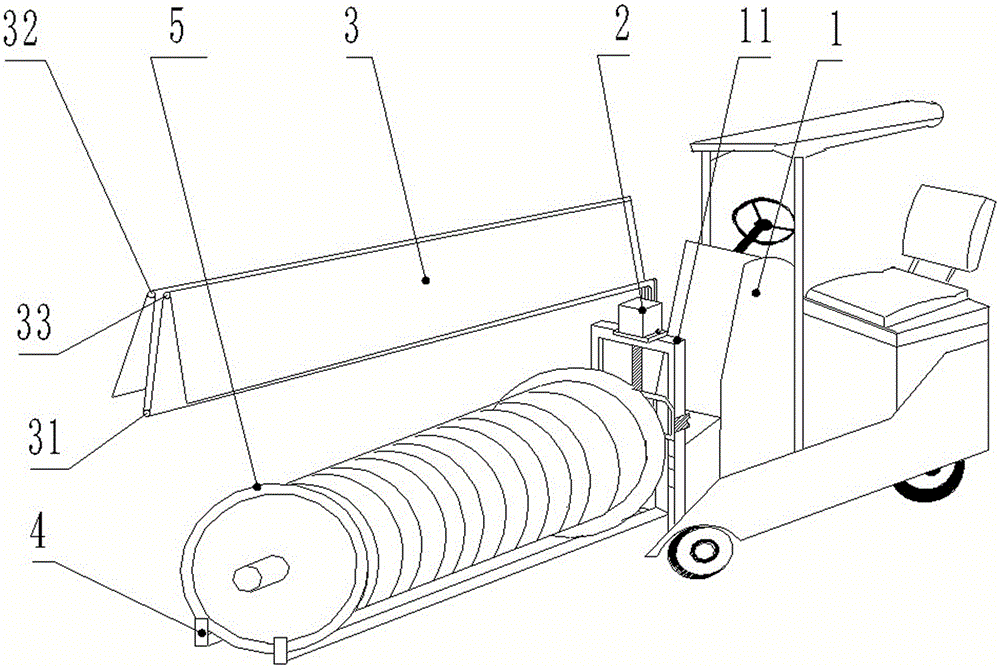
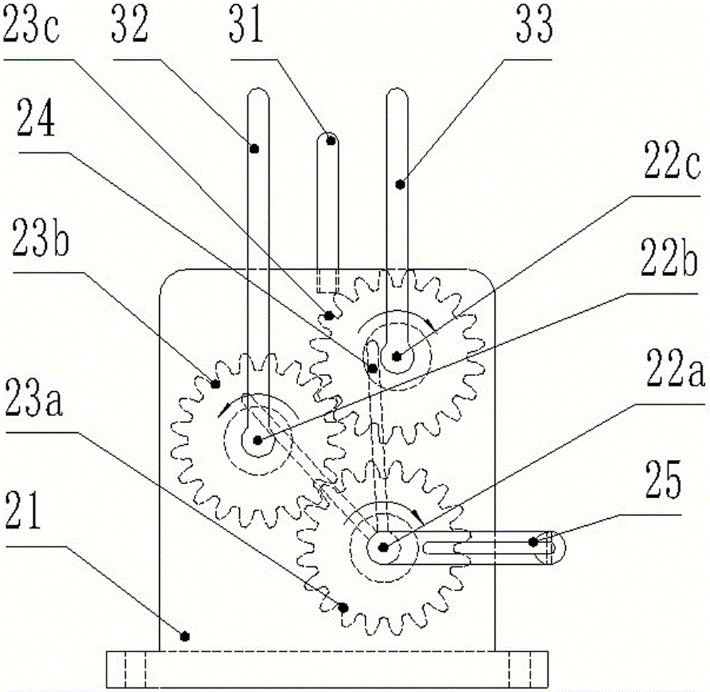
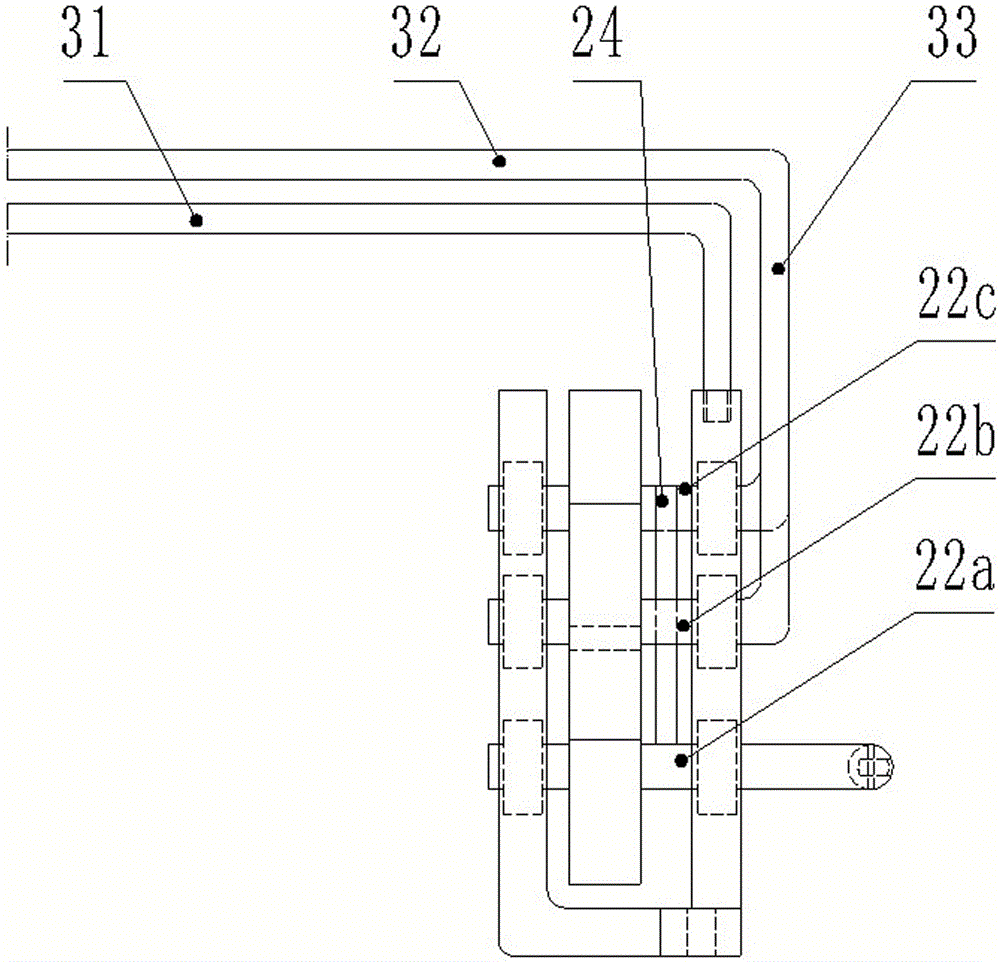
[0017] Such as Figure 1 to Figure 6 It can be seen that the self-locking special weaving shaft transport vehicle for textile of the present invention includes a forklift 1, the front end of the electric forklift 1 is provided with a door frame 11, the upper end of the door frame 11 is provided with a remote control device 2, and also includes a The first bracket 31 in the shape of "¬" above, the remote control device 2 includes a frame 21 in the shape of "凵", on which the first optical axis 22a, the first optical axis 22a, the second The second optical axis 22b, the third optical axis 22c, the middle parts of the first optical axis 22a, the second optical axis 22b, and the third optical axis 22c are respectively provided with a first gear 23a, a second gear 23b, and a third gear 23c, The first gear 23a and the second gear 23b, the second gear 23b and the third gear 2...


PUM


Abstract

The invention provides a self-locking weaving-shaft transport vehicle special for spinning. The carrying strength can be reduced, the transport safety can be improved, and operation is easy and convenient. The self-locking weaving-shaft transport vehicle comprises a forklift. A gantry is arranged at the front end of the electric forklift. A remote control device is arranged at the upper end of the gantry. The self-locking weaving-shaft transport vehicle further comprises a transverse-L-shaped first support arranged above the forklift. The remote control device comprises a U-shaped frame. A first polished shaft, a second polished shaft and a third polished shaft are arranged on the U-shaped frame through bearings. A first gear, a second gear and a third gear are arranged in the middle of the first polished shaft, the middle of the second polished shaft and the middle of the third polished shaft respectively. The first gear is in transmission fit with the second gear, and the second gear is in transmission fit with the third gear. A transverse-L-shaped second support is arranged at the tail end of the second polished shaft. A transverse-L-shaped third support is arranged at the tail end of the third polished shaft. A rainproof shed is arranged among the first support, the second support and the third support in a stretchable mode. The self-locking weaving-shaft transport vehicle further comprises a left L-shaped fork frame and a right L-shaped fork frame which are arranged at the lower end of the gantry.

Description

technical field [0001] The invention relates to an electric transport vehicle, in particular to a special weaving shaft transport vehicle for textiles. Background technique [0002] In the textile industry, the whole bobbin of spinning cloth is wound onto a large shaft, ready to be placed on the loom for weaving. This shaft is called a weaving shaft. The function of the weaving beam transport vehicle is to transport the above-mentioned weaving beams wound with package yarns from the machine position to the storage rack in the workshop for storage, and then transport the weaving beams to each loom table to prepare for weaving according to production needs. The process may be transportation within the workshop, or transportation between two workshops. The weight of the weaving shaft is more than 300kg. Generally, the operator completes this work by means of manual hydraulic vehicle transportation, but it involves transportation between workshops. Due to the long distance and ...

Claims


Application Information

Patent Timeline
Patent Type & Authority Applications(China)
IPC IPC(8): B66F9/06B66F9/075B66F9/12
CPCB66F9/06B66F9/07504B66F9/12
Inventor 郭明
Owner 安徽泰阳织造科技有限公司
Why Eureka
Try Eureka