Grating magnetic separation type sewage treatment apparatus

A kind of sewage treatment equipment and magnetic separation technology, applied in the direction of magnetic field/electric field water/sewage treatment, water/sewage multi-stage treatment, water/sludge/sewage treatment, etc., can solve the problem of limited water treatment, high manufacturing cost and complex process and other issues to achieve the effect of ensuring the use effect and service life, cleaning thoroughly, and expanding the amount of treated water

Active Publication Date: 2015-11-18
ANHUI PUSHI ECOLOGICAL ENVIRONMENT ENG
View PDF6 Cites 6 Cited by
  • Summary
  • Abstract
  • Description
  • Claims
  • Application Information

AI Technical Summary

Problems solved by technology

At present, the existing magnetic separation water treatment equipment is mainly based on magnetic disk drives, but the manufacturing process of magnetic disk drives is relatively complicated, the manufacturing cost is high, and there are defects such as more slag leakage and limited treatment water volume.

Method used


Image

  • Grating magnetic separation type sewage treatment apparatus
  • Grating magnetic separation type sewage treatment apparatus
  • Grating magnetic separation type sewage treatment apparatus

Examples


Embodiment 1

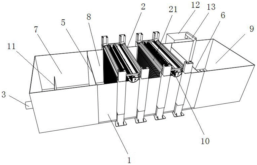
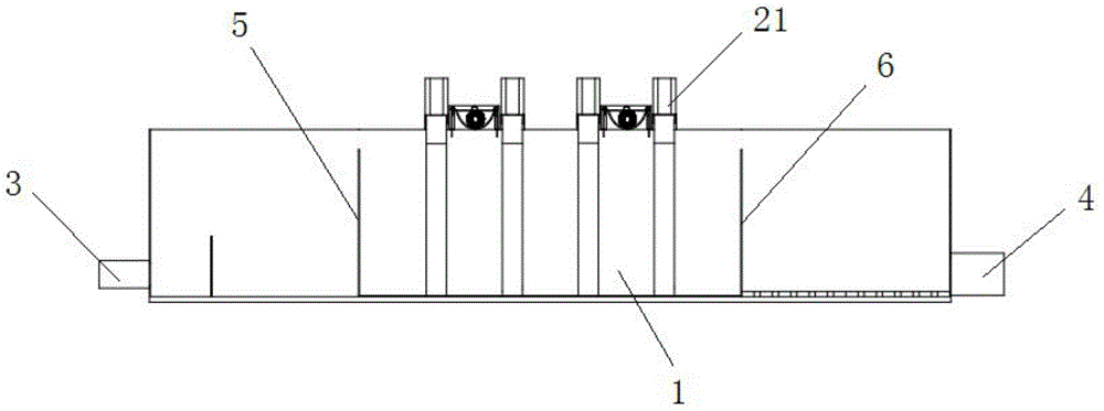
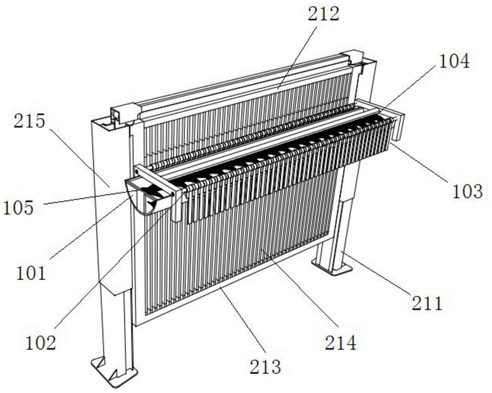
[0031] In this example, see image 3 and Figure 4 A slag removal device 10 for scraping and collecting magnetic slag on the magnetic strip 214 is provided on one side of the magnetic separation grid 21 . The slag removal device 10 is located at the upper part between two adjacent magnetic separation grids 21, and includes a magnetic slag collection tank 101 horizontally arranged on the surface of the movable grid group 212, see figure 1 , the length of the magnetic slag collecting tank 101 is equal to or greater than the width of the magnetic separation cabinet 1, the magnetic slag collecting tank 101 is provided with a scraper shaft 102 on both sides, and the scraper shaft 102 is provided with the same number as the magnetic strip 214, which can be inserted into the adjacent Between the magnetic strips 214, the scraper 103 for scraping off the magnetic slag on the surface of the magnetic strip 214, the magnetic slag collection tank 101 is provided with a cleaning brush 104 ...

Embodiment 2

[0034] In this embodiment, the height of the magnetic separation grid 21 is greater than the height of the magnetic separation cabinet 1 . The purpose is to ensure the installation height of the magnetic strip 214 so that it can complete the adsorption of magnetic slag in a wide range, improve the purification quality, and maximize the water treatment capacity.

Embodiment 3

[0036] In this embodiment, a buffer baffle 11 is provided near the water inlet 3 in the water inlet pool 7 . The purpose is to control the speed of water flow when water enters, so as to prevent the water from flowing too fast and having a large impact on the first perforated wall 5 , thus affecting the service life and purification effect of the first perforated wall 5 .


PUM


Abstract

The invention discloses a grating magnetic separation type sewage treatment apparatus. The apparatus comprises a magnetic separation cabinet, the middle portion of the magnetic separation cabinet is provided with a grating magnetic separation purifier, two sides of the magnetic separation cabinet are respectively provided with a water inlet and a water outlet, two sides of the grating magnetic separation purifier in the magnetic separation cabinet are respectively provided with a first perforated wall and a second perforated wall, an inlet water pool is formed between the first perforated wall and the water inlet of the magnetic separation cabinet, a purifying pool is formed between the first perforated wall and the second perforated wall, an outlet water pool is formed between the second perforated wall and the water outlet of the magnetic separation cabinet, and the inlet water pool, the purifying pool and the outlet water pool are sequentially communicated. The apparatus has the advantages of simple structure and convenient manufacturing, allows the speed of water flow in the grating magnetic separation purifier to be stably controlled through using the first perforated wall and the second perforated wall and cooperating with the purifying pool formed by the grating magnetic separation purifier, allows water to be effectively and comprehensively cleaned through the grating magnetic separation purifier, and ensures adaption to large sewage throughout.

Description

technical field [0001] The invention relates to sewage treatment equipment, in particular to grid magnetic separation type sewage treatment equipment. Background technique [0002] The scarcity of water resources, sustained economic growth, and population increase will inevitably lead to continuous increases in water prices. Therefore, vigorously developing the cause of sewage reuse can not only save limited water resources, alleviate the increasingly prominent water shortage, but also Reduce sewage discharge, reduce pollution to surrounding water bodies, improve human living environment, and save a lot of water resource fees. Sewage reuse is an important measure to promote the coordinated development of economy, environment and society, and there are huge business opportunities. [0003] Magnetic separation technology can be said to be a relatively old and mature technology, which was first used in mineral processing and china clay industry, while magnetic separation techn...

Claims


Application Information

Patent Timeline
Patent Type & Authority Applications(China)
IPC IPC(8): C02F1/48C02F9/12
Inventor 张宁迁
Owner ANHUI PUSHI ECOLOGICAL ENVIRONMENT ENG
Why Eureka
Try Eureka