Moving drill rod of cement-soil mixing pile driver

A technology of cement-soil mixing pile and pile driver, which is applied in the directions of earth-moving drilling, impact drilling, rotary drilling, etc., can solve the problems such as the inability to drill the drill pipe, the low drilling efficiency and the difficulty of drilling, etc. Achieve the effect of easy drilling, improve efficiency, and improve pullout resistance

Active Publication Date: 2015-11-18
周兆弟
View PDF7 Cites 51 Cited by
  • Summary
  • Abstract
  • Description
  • Claims
  • Application Information

AI Technical Summary

Problems solved by technology

The above scheme solves the problem of low drilling efficiency of the existing cement-soil mixing pile machine to a certain

Method used


Image

  • Moving drill rod of cement-soil mixing pile driver
  • Moving drill rod of cement-soil mixing pile driver
  • Moving drill rod of cement-soil mixing pile driver

Examples


Embodiment Construction

[0023] The present invention will be described in further detail below in conjunction with the accompanying drawings and specific embodiments.

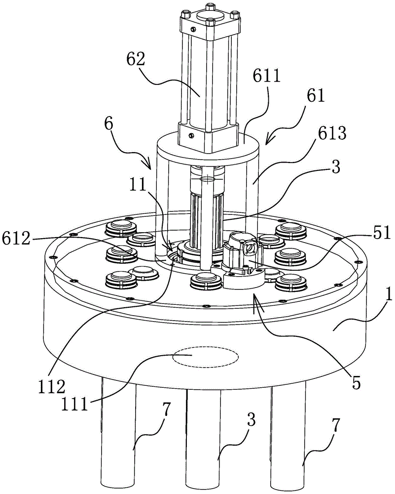
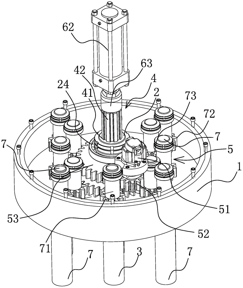
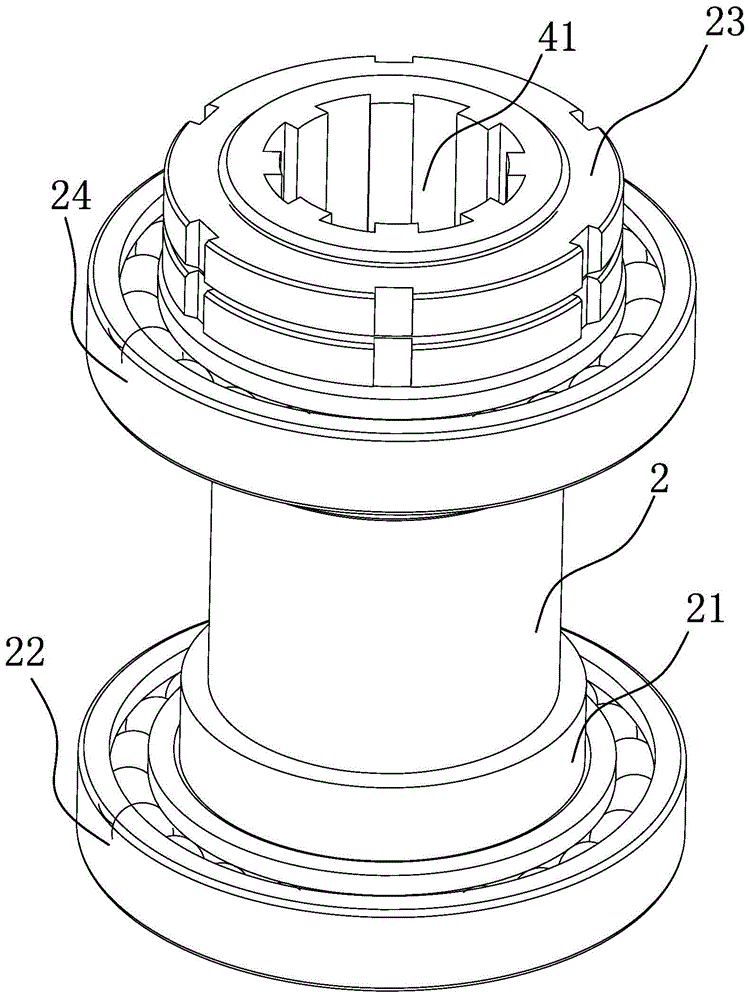
[0024] Such as Figure 1-3 As shown, the movable drill rod of the cement-soil mixing pile driver includes a drive box 1 with an inner cavity, and the drive box 1 is provided with at least one through hole 11 axially penetrating through the entire drive box 1, and the through hole 11 is provided with a cylindrical guide sleeve 2 that can rotate in the circumferential direction, and a drill rod 3 that runs through the entire drive box 1 is pierced in the guide sleeve 2, and a drill rod 3 is provided between the drill rod 3 and the guide sleeve 2. The rod 3 and the guide sleeve 2 are circumferentially positioned and axially slidably connected to the axial guide structure 4. The guide sleeve 2 is connected with a circumferential rotation mechanism 5 that can drive the guide sleeve 2 to rotate in the circumferential direction. The drill pi...


PUM


Abstract

The invention belongs to the technical field of building equipment, and particularly relates to a moving drill rod of a cement-soil mixing pile driver. The moving drill rod solves the problem that existing cement-soil mixing pile drivers are prone to drill failures when drilling and the like, and comprises a driving box with an inner cavity, wherein the driving box is provided with at least one through hole which runs through the whole driving box in the axial direction; a guiding sleeve which can rotate in the circumferential direction and is cylindrical is arranged in the through hole; a drill rod which runs through the whole driving box is arranged in the guiding sleeve in a penetrating manner; an axial guiding structure is arranged between the drill rod and the guiding sleeve; the guiding sleeve is connected with a circumferential rotating mechanism which can drive the guiding sleeve to rotate in the circumferential direction; and the drill rod is connected with an axial driving mechanism which can drive the drill rod to slide back and forth in the axial direction. The moving drill rod of the cement-soil mixing pile driver has the advantages that a drill rod body can stretch in the axial direction, can rotate in the circumferential direction and slide in the axial direction at the same time, and thus is not prone to rotation failures; the perimeter of the cross section of a cement-soil mixing pile after constructing is increased; and the pull-out capacity of the cement-soil mixing pile is improved.

Description

technical field [0001] The invention belongs to the technical field of construction equipment, in particular to a movable drill pipe of a cement-soil mixing pile driver. Background technique [0002] The cement-soil mixing pile is a method for reinforcing the low foundation of saturated soft clay. It uses cement as the curing agent, and through a special mixing machine, the soft soil and the curing agent are forced to mix deep in the foundation. A series of physical and chemical reactions between them make the soft soil harden into a high-quality foundation with integrity, water stability and certain strength. Common pile drivers for cement-soil mixing piles mostly use the drive box to drive the drill pipe to rotate, and the drive box is lifted as a whole to move the drill pipe downward. During the use of this cement-soil mixing pile machine, when the drill pipe meets the hard soil Or the situation that the stone cannot rotate, it is necessary to lift the whole drive box an...

Claims


Application Information

Patent Timeline
IPC IPC(8): E21B3/02E02D5/46
CPCE02D5/46E21B3/02E21B3/022
Inventor 周兆弟
Owner 周兆弟
Why Eureka
Try Eureka