Integrated fuel tank structure for amphibious ships

An amphibious and integrated technology, applied in the direction of fuel supply tank device, fluid pressure actuation device, fluid pressure actuation system components, etc., it can solve the problems of affecting the heat dissipation effect, increasing the ambient temperature, and being unable to apply, so as to prevent leakage The hidden danger of oil, the effect of improving safety performance and improving heat dissipation efficiency

Active Publication Date: 2017-10-03
江阴荣兴科技发展有限公司
View PDF9 Cites 0 Cited by
  • Summary
  • Abstract
  • Description
  • Claims
  • Application Information

AI Technical Summary

Problems solved by technology

[0002] At present, the hydraulic station needs to be used on the amphibious ship to provide power for the steering system; at the same time, in consideration of safety and system stability, it is necessary to cool the hydraulic oil in the oil tank of the hydraulic station. The conventional cooling method needs to be installed in the hydraulic control valve block. Add a heat dissipation oil channel on the top to circulate the hydraulic oil in the oil tank to the heat exchanger / radiator for circulation and heat dissipation; this method requires an additional oil channel. For the oil system, the more oil channels It also means more potential oil leakage risks, so this method cannot be applied to some occasions with high safety factor requirements; at the same time, heat dissipation is carried out through the radiator / heat exchanger, and only a small part of the hydraulic pressure is used in the continuous cycle process. The oil enters the heat exchanger / radiator to dissipate heat, the efficiency is low, and the heat exchanger / radiator also does not generate a certain amount of heat during the working process, and the installation space of the hydraulic station is often small, so a new heat exchanger is added at this time / The heat generated by the radiator will undoubtedly increase the ambient temperature in the space, which will also affect the heat dissipation effect; on the other hand, since the amphibious ship travels on soft surfaces such as tidal flats and beaches, there are strict restrictions on its own weight;
[0003] For this reason, some companies have applied "a fuel tank with heat dissipation fins" as disclosed in Chinese patent application 201310719952.4, and avoided the conventional heat dissipation method of additional heat exchangers / radiators by arranging heat dissipation fins outside the fuel tank The heat dissipation of the hydraulic oil in the oil tank is carried out by means of fins; however, this way of heat dissipation directly through the heat dissipation fins is passive heat dissipation, and the efficiency is low; and because the installation space of the hydraulic station is small, the heat dissipated passively at this time still accumulates In this space, when the hydraulic station system works for a period of time, due to the rise of the ambient temperature in this space, the heat dissipation fins will not be able to continue to dissipate heat to the hydraulic oil in the hydraulic oil tank, thus affecting the heat dissipation effect of the oil tank

Method used


Image

  • Integrated fuel tank structure for amphibious ships
  • Integrated fuel tank structure for amphibious ships

Examples


Embodiment Construction

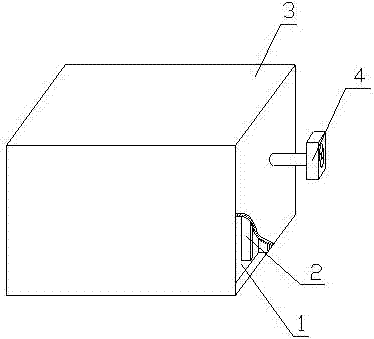
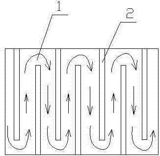
[0018] see Figure 1~2 , the present invention relates to an integrated fuel tank structure for amphibious ships, the structure includes a fuel tank body 1, the fuel tank body 1 is wrapped with a casing 3, the outer tank wall and the cover of the fuel tank body 1 A heat dissipation cavity is formed between the inner shell walls of the shell 3, and a plurality of heat dissipation fins 2 are arranged in parallel in the heat dissipation cavity, and the two sides of the heat dissipation fins 2 are respectively connected to the outer tank wall and the cover On the inner shell wall of the shell 3, the heat dissipation fins 2 are arranged in a staggered manner (staggered up and down or left and right, as shown in Figure 2). The heat dissipation cavity between the two separates the serpentine heat dissipation channel, so that the air flowing through it must go forward along the serpentine heat dissipation channel, which increases the heat dissipation length and heat dissipation time, ...


PUM


Abstract

The invention relates to an integrated oil tank structure for an amphibious ship. The structure comprises an oil tank body (1), the oil tank body (1) is covered with a shell (3), and a cooling cavity is formed between the outer tank wall of the oil tank body (1) and the inner shell wall of the shell (3). A plurality of cooling fins (2) are arranged in the cooling cavity in parallel. The cooling fins (2) are arranged in a staggered mode. An air inlet and an air outlet are formed in the outer shell wall of the shell (3). The integrated oil tank structure for the amphibious ship is high in cooling efficiency and good in effect.

Description

technical field [0001] The invention relates to a fuel tank structure, in particular to a fuel tank structure applied to an amphibious ship and having a strong air-cooling effect, and belongs to the technical field of amphibious ship-related equipment. Background technique [0002] At present, the hydraulic station needs to be used on the amphibious ship to provide power for the steering system; at the same time, in consideration of safety and system stability, it is necessary to cool the hydraulic oil in the oil tank of the hydraulic station. The conventional cooling method needs to be installed in the hydraulic control valve block. Add a heat dissipation oil channel on the top to circulate the hydraulic oil in the oil tank to the heat exchanger / radiator for circulation and heat dissipation; this method requires an additional oil channel. For the oil system, the more oil channels It also means more potential oil leakage risks, so this method cannot be applied to some occasi...

Claims


Application Information

Patent Timeline
Patent Type & Authority Patents(China)
IPC IPC(8): F15B1/26F15B21/04
CPCF15B1/26F15B21/042
Inventor 张云
Owner 江阴荣兴科技发展有限公司
Why Eureka
Try Eureka