Wheel hub unit

A hub unit and hub technology, applied in engine components, engine sealing, engine lubrication, etc., can solve the problems of limited oil sealing effect of outer oil seal, inability to replenish oil film in time, and oil film volatilization, etc., to improve the use environment and function. Improved life and stable polymer properties

Active Publication Date: 2015-11-18
SHANDONG HAOXIN MACHINERY
View PDF11 Cites 3 Cited by
  • Summary
  • Abstract
  • Description
  • Claims
  • Application Information

AI Technical Summary

Problems solved by technology

During use, due to the lubricating oil inside the inner oil seal, its working condition is good, but the outer oil seal is exposed to the natural environment for a long time, the oil film will evaporate in a short time, and the oil film cannot be replenished in time, so that the outer oil seal is in dry friction state, leading to premature failure of the outer oil seal
Therefore, the life of the outer oil seal is shorter than that of the inner oil seal with the same material. In fact, only the inner oil seal can effectively block oil in the double oil seal structure, and the oil sealing effect of the outer oil seal is very limited.

Method used


Image

  • Wheel hub unit
  • Wheel hub unit
  • Wheel hub unit

Examples


Embodiment 1

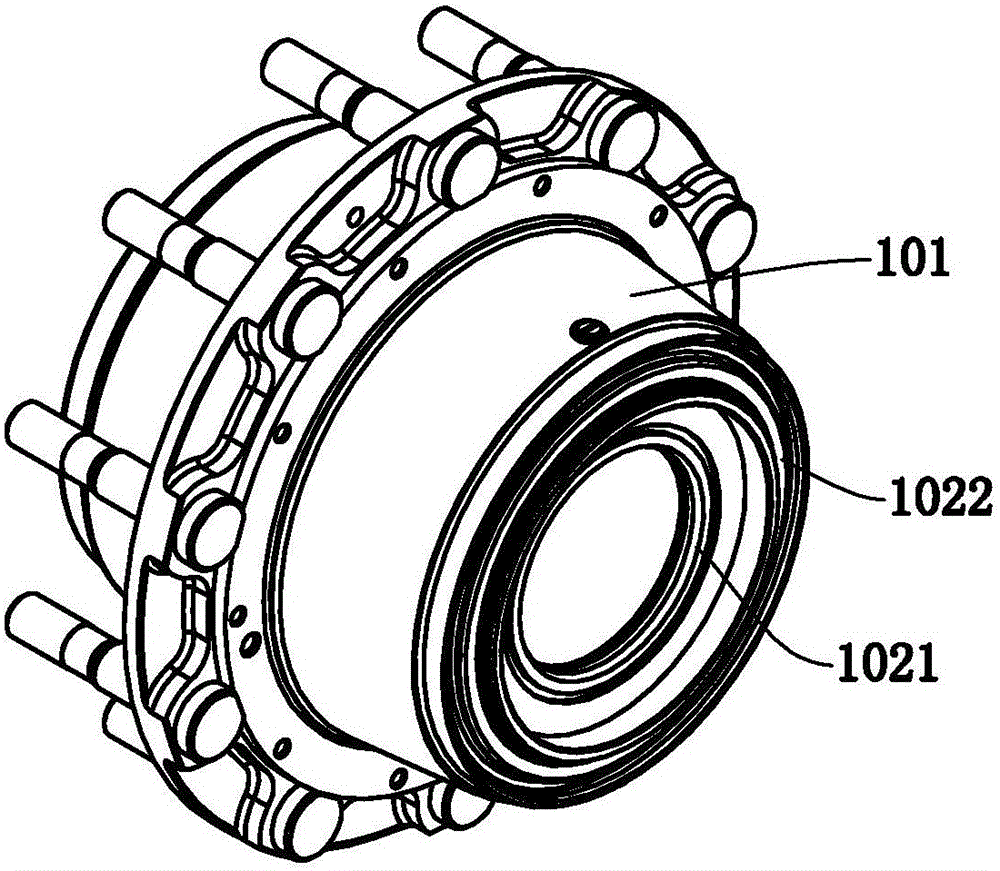
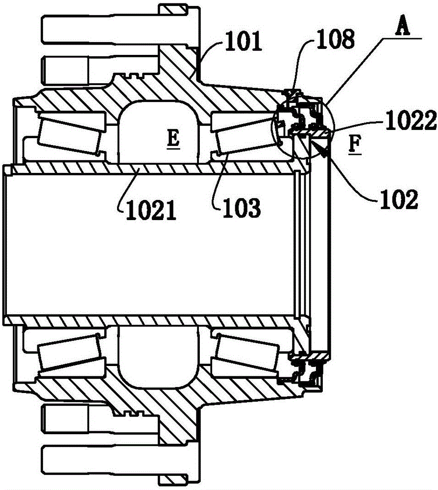
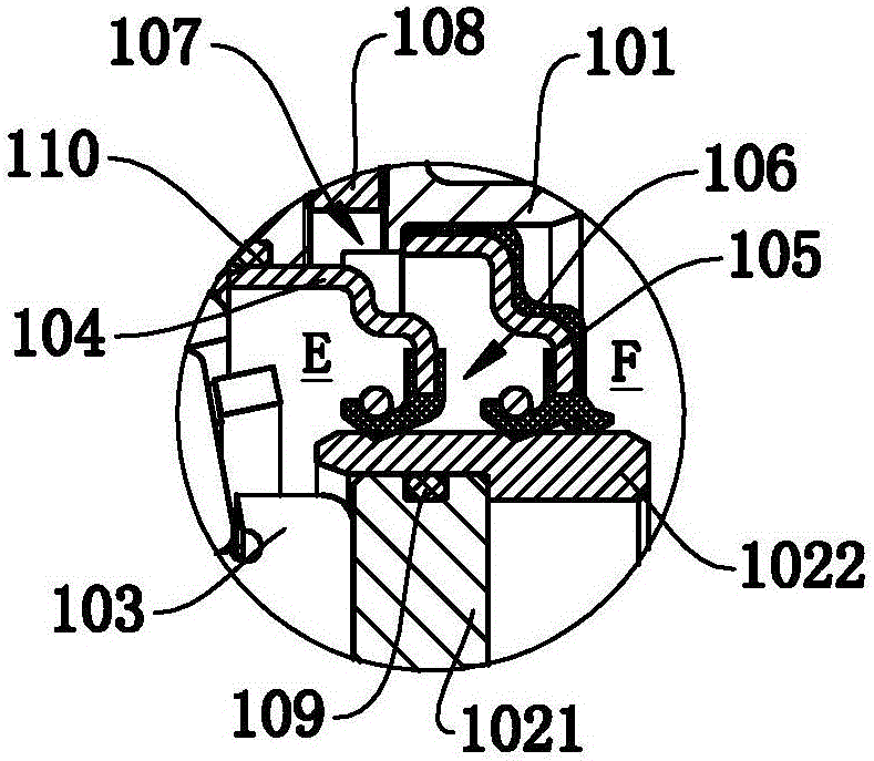
[0024] Such as Figure 1 to Figure 3 Commonly shown, a hub unit, the shaft sleeve 102 runs through the hub body 101, and is installed on the hub body 101 through the bearing 103, and a first sealing ring 104 is provided between the sealing surface of the hub body 101 and the sealing surface of the shaft sleeve 102 and the second sealing ring 105 , along the axial direction, the inner side of the first sealing ring 104 is the sealing area E, and the outer side of the second sealing ring 105 is the atmospheric area F.

[0025] An oil storage cavity 106 is formed between the sealing surface of the hub body 101, the sealing surface of the shaft sleeve 102, and the first sealing ring 104 and the second sealing ring 105, and the hub body 101 is provided with an oil filling hole for filling the oil storage cavity 106 107, the oil injection hole 107 is provided with a screw plug 108.

[0026] Due to the design of an independent oil storage chamber 106, special lubricating oil for sea...

Embodiment 2

[0033] Such as Figure 4 to Figure 6 Commonly shown, a hub unit, the shaft sleeve 202 runs through the hub body 201, and is installed on the hub body 201 through the bearing 203, and a first sealing ring 204 is provided between the sealing surface of the hub body 201 and the sealing surface of the shaft sleeve 202 and the second sealing ring 205 , along the axial direction, the inner side of the first sealing ring 204 is the sealing area E, and the outer side of the second sealing ring 205 is the atmospheric area F.

[0034] An oil storage cavity 206 is formed between the sealing surface of the hub body 201, the sealing surface of the shaft sleeve 202, and the first sealing ring 204 and the second sealing ring 205, and the hub body 201 is provided with an oil filling hole for filling the oil storage cavity 206 207, the oil injection hole 207 is provided with a screw plug 208.

[0035] In this embodiment, lubricating oil is injected into the oil storage chamber 206 from the oi...


PUM


Abstract

The invention discloses a wheel hub unit. The wheel hub unit comprises a wheel hub body, a shaft sleeve and a bearing. A first sealing ring and a second sealing ring are arranged between the sealing face of the wheel hub body and the sealing face of the shaft sleeve. The inner side of the first sealing ring is a sealing zone and the outer side of the second sealing ring is an atmosphere zone in the axis direction. An oil-storing cavity is formed among the sealing face of the wheel hub body, the sealing face of the shaft sleeve, the first sealing ring and the second sealing ring. An oil filler hole is formed in the wheel hub body. A screw-plug is arranged on the oil filler hole. According to the oil fluid microcosmic motion principle, the functional life of lubricating oil is prolonged; sealing lips of the sealing rings can maintain lubricating oil films; even through one sealing ring is invalid, the other sealing ring can still play a sealing function, so that the service environment of the sealing rings is improved, the service life of the sealing rings is prolonged and the sealing rings are convenient to disassemble.

Description

technical field [0001] The invention relates to the technical field of vehicle hubs, in particular to a hub unit lubricating its bearings with lubricating oil. Background technique [0002] For the bearings in the hub unit, oil lubrication and grease lubrication are usually used. The sealing structure of grease lubrication is relatively simple, but during maintenance, the bearing needs to be replaced or removed. The maintenance of oil lubrication is relatively simple, you only need to drain the lubricating oil and refill it. This advantage makes oil lubrication the mainstream direction of the wheel hub units of trucks, buses and other vehicles. However, oil lubrication will be affected by comprehensive factors such as temperature, heavy load, and impact load, and it is easy to leak oil, so higher requirements are put forward for the sealing structure. [0003] In the prior art, an oil seal is usually used to seal the lubricating oil. In order to ensure the sealing effect, ...

Claims


Application Information

Patent Timeline
Patent Type & Authority Applications(China)
IPC IPC(8): F16J15/16F16N7/00
CPCF16J15/16F16N7/00
Inventor 吕继贤蒲光明高世阳
Owner SHANDONG HAOXIN MACHINERY
Why Eureka
Try Eureka