Sealing ring special for piston of injector of pipe-free liquid dropping machine

A technology for syringes and sealing rings, which is applied in the field of special sealing rings for syringe pistons of pipeless liquid drip machines, which can solve the problems of unfavorable liquid dosing actuator stability control, liquid dosing accuracy errors, and prone to crawling phenomena, etc.

Active Publication Date: 2015-11-18
HUAQIAO UNIVERSITY +1
View PDF6 Cites 4 Cited by
  • Summary
  • Abstract
  • Description
  • Claims
  • Application Information

AI Technical Summary

Problems solved by technology

On the one hand, due to the self-sealing principle of the U-shaped sealing ring and the O-shaped sealing ring, the friction force and starting force are relatively large during the movement process, which is prone to crawling, which is not conducive to the stable control of the liquid distribution actuator, so that the distribution On the other hand, the U-shaped sealing ring and O-shaped sealing ring will produce large elastic deformation during the operation of the syringe piston, and this deformation will slowly recover when the syringe piston is stationary, and the recovery of the deformation of the sealing ring It will cause the corresponding displacement of the syringe piston, which will affect the injection volume of the dye liquid and affect the accuracy of dosing

Method used


Image

  • Sealing ring special for piston of injector of pipe-free liquid dropping machine
  • Sealing ring special for piston of injector of pipe-free liquid dropping machine
  • Sealing ring special for piston of injector of pipe-free liquid dropping machine

Examples


Embodiment 1

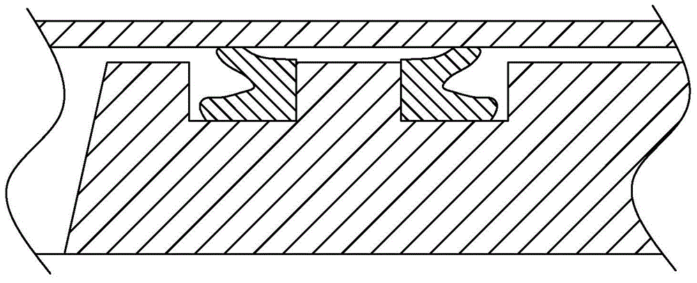
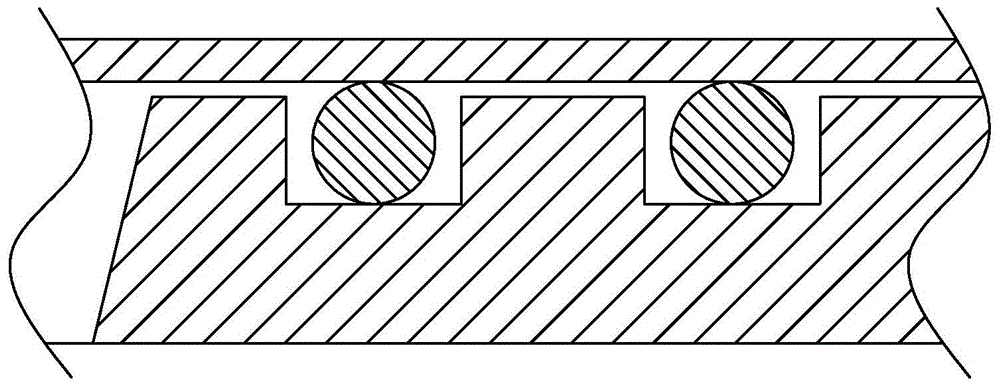
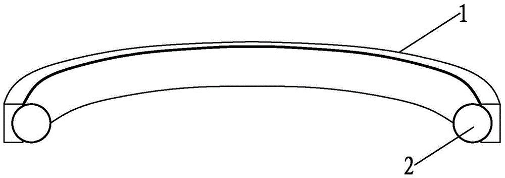
[0026] A special sealing ring for the syringe piston of a pipeless dripping machine, such as Figure 3-6 As shown, it includes a sealing outer ring 1 that is in interference and sealing contact with the inner wall of the syringe cylinder 10 and a sealing inner ring 2 that is in interference and sealing contact with the installation groove 30 of the syringe piston 20. The longitudinal section of the sealing outer ring 1 is in the shape of an arch bridge. , the sealing inner ring 2 is an O-shaped sealing ring, and the side surface of the sealing outer ring 1 facing away from the inner wall of the syringe cylinder 10 is provided with an arc-shaped groove 11, and the sealing inner ring 2 is partially embedded in the arc-shaped groove 11 and is connected with the The arc groove 11 is in interference sealing contact.

[0027] The installation method of a special sealing ring (abbreviated as the sealing ring) for the syringe piston of a pipeless liquid dripping machine of the present...

Embodiment 2

[0033] In this example, if Figure 7 As shown, the front end of the syringe piston 20 is provided with two installation grooves 30 along its outer periphery, and two sealing rings of the present invention are respectively sleeved in each installation groove 30, so that the sealing inner ring of each sealing ring 2 is in sealing contact with the groove bottom of the corresponding installation groove 30, and the sealing outer ring 1 of each sealing ring is in sealing contact with the corresponding position of the inner wall of the syringe cylinder 10. This setting can not only achieve a better sealing effect, but also play a guiding role for the dye entering the cylinder of the syringe.


PUM


Abstract

The invention discloses a sealing ring special for a piston of an injector of a pipe-free liquid dropping machine. The sealing ring comprises an outer sealing ring body in interference sealing contact with the inner wall of a cylinder of the injector and an inner sealing ring body in interference sealing contact with an installation groove of the piston of the injector. The inner sealing ring body is in an O shape. An arc-shaped groove is formed in one side face, back to the inner wall of the cylinder of the injector, of the outer sealing ring body. The part of the inner sealing ring body is embedded in the arc-shaped groove and is interference sealing contact with the arc-shaped groove. By the adoption of the sealing ring special for the piston of the injector of the pipe-free liquid dropping machine, friction force and start force in the moving process of the piston of the injector are reduced, the crawling phenomenon is eliminated, and the sealing ring is resistant to a medium and small in deformation in the moving process.

Description

technical field [0001] The invention relates to a sealing ring, in particular to a special sealing ring for a syringe piston of a pipeless drip machine. Background technique [0002] As a relatively advanced dye automatic color matching system, the pipeless drip system is widely used in the production and scientific research fields related to dye color matching, such as printing and dyeing enterprises, university laboratories and laboratories. With the improvement of the technical level, the pipeless liquid drip system has completely replaced the traditional manual liquid suction operation method, and the color matching operation process is completely controlled by the computer, which not only reduces the labor intensity of the workers, but also improves the liquid preparation. accuracy and efficiency. [0003] The traditional pipeless drip machine syringe piston is sealed with a U-shaped sealing ring or only an O-shaped sealing ring, such as figure 1 and figure 2 As sho...

Claims


Application Information

Patent Timeline
Patent Type & Authority Applications(China)
IPC IPC(8): F16J15/16
CPCF16J15/16
Inventor 付胜杰汤瑞能
Owner HUAQIAO UNIVERSITY
Why Eureka
Try Eureka