Sensor coupling device and damping debugging method suitable for vibration/fluctuation test

A technology of coupling device and debugging method, which is applied to the components of the damping part of the measuring device, the measuring device, and the measurement of ultrasonic/sonic/infrasonic waves, etc., can solve the problems of low test efficiency and unstable frequency response characteristics of the sensor system, and achieve reduction The effect of small bad contact, improved frequency response range, and stable test signal

Active Publication Date: 2018-04-24
四川升拓检测技术股份有限公司
View PDF7 Cites 0 Cited by
  • Summary
  • Abstract
  • Description
  • Claims
  • Application Information

AI Technical Summary

Problems solved by technology

[0006] In order to solve the defects of unstable frequency response characteristics and low test efficiency of existing sensor systems, the present invention provides a sensor coupling device and damping debugging method suitable for vibration / fluctuation testing

Method used


Image

  • Sensor coupling device and damping debugging method suitable for vibration/fluctuation test
  • Sensor coupling device and damping debugging method suitable for vibration/fluctuation test
  • Sensor coupling device and damping debugging method suitable for vibration/fluctuation test

Examples


Embodiment 1

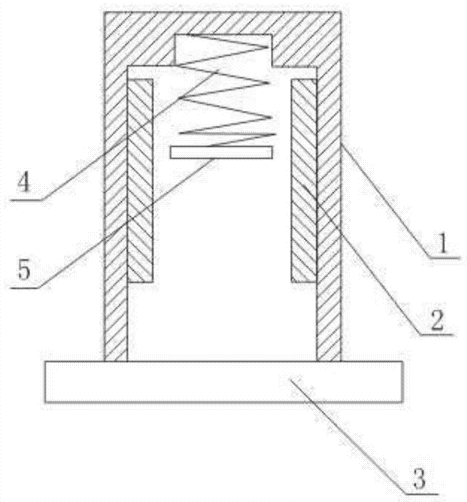
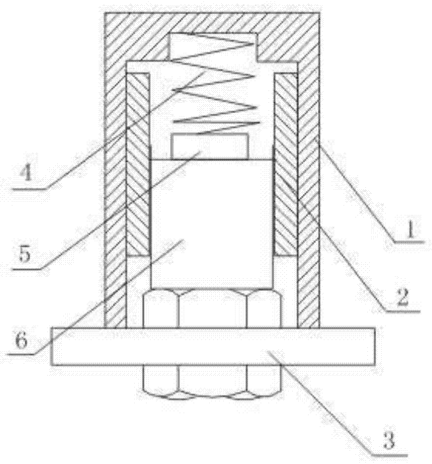
[0045] Such as figure 1 , figure 2 , image 3 As shown, the sensor coupling device suitable for vibration / fluctuation testing includes a headgear 1, a deck 2 set in the headgear 1, and a base 3 fixed at the lower end of the headgear 1. Both the headgear 1 and the deck 2 are hollow structures, and the headgear The lower end of 1 is open, the upper and lower surfaces of the deck 2 are open, and the deck 2 is clamped in the inner cavity of the headgear 1; the inner wall of the deck 2 is coated with a couplant connected with the sensor 6; the upper surface of the base 3 is provided with a sensor 6 holes through which the lower end passes. It also includes a coupling agent arranged between the outer wall of the card seat 2 and the inner wall of the headgear 1 . It also includes a spring 4 and a rubber gasket 5 arranged in the headgear 1 , one end of the spring 4 is connected with the top of the headgear 1 , and the other end is connected with the rubber gasket 5 . The base 3 i...

Embodiment 2

[0086] A damping debugging method for a sensor coupling device suitable for vibration / fluctuation testing, comprising the following steps:

[0087] Include the following steps:

[0088] a) Insert the sensor 6 into the deck 2, and make the lower end of the sensor 6 pass through the hole on the base 3. In this state, a part of the lower end of the sensor 6 will be exposed from the base 3;

[0089] b) Loosen the sensor 6 to make it return to the free state under the action of the spring, and measure its required recovery time t 1 ;

[0090] c) According to the spring coefficient k of the elastic spring z , the natural frequency ω of the sensor 6 system, the mass m of the sensor 6 system, calculate the time t that should be restored after the card holder 2 is coated with coupling agent 2 ;

[0091] d) will test the obtained t 1 with t 2 For comparison, if t 1 fall into t 2 In the range of , the smeared couplant meets the damping ratio requirements required by the test syst...


PUM


Abstract

The invention describes a sensor coupling device and a damping debugging method suitable for vibration/fluctuation testing, including a headgear, a card holder arranged in the headgear, and a base fixed at the lower end of the headgear. Both the headgear and the holder are cavity structures, and the lower end of the headgear is open The upper and lower surfaces of the deck are open, and the deck is clamped in the inner cavity of the headgear; the inner wall of the deck is coated with a couplant connected with the sensor; the upper surface of the base is provided with a hole for the lower end of the sensor to pass through. It also includes a coupling agent arranged between the outer wall of the card seat and the inner wall of the headgear. In the present invention, the setting of the card seat provides a lateral damping for the sensor and limits the lateral displacement of the sensor, and the couplant filled between the inner wall of the base and the sensor and the outer wall of the card seat and the inner wall of the headgear does not reduce the sensor and sensor. The viscosity of the test system is increased under the premise of rigid contact of the measured object, the frequency response range of the test system is improved, and the dynamic error is reduced.

Description

technical field [0001] The invention relates to a sensor coupling device and a damping debugging method, in particular to a sensor coupling device and a damping debugging method suitable for vibration / fluctuation testing. Background technique [0002] In the test of vibration and fluctuation, it is currently the most mainstream way to pick up the vibration signal of the structure under test by the sensor, and the sensing system (including sensor and coupling mode) has the most direct influence on the test signal. [0003] The main indicators of the sensor include quality, sensitivity, frequency response range, natural frequency, lateral sensitivity, temperature range, and impact resistance. The most important indicators are the quality, sensitivity and frequency response range of the sensor. Regarding the mass of the sensor, if the dynamic mass of the accelerometer is close to the dynamic mass of the structure to be measured, the vibration will be significantly attenuated a...

Claims


Application Information

Patent Timeline
Patent Type & Authority Patents(China)
IPC IPC(8): G01H17/00G01D11/10
Inventor 吴佳晔朱纪刚孔元罗技明吴曾炜
Owner 四川升拓检测技术股份有限公司
Why Eureka
Try Eureka