
Current measuring method and device

A current measurement and current technology, applied in measurement devices, measurement of electrical variables, measurement of current/voltage, etc., can solve problems such as zero point drift, limiting product measurement accuracy, and output zero point stability.

Active Publication Date: 2015-11-18
SHENZHEN XINRUIDA ELECTRIC POWER EQUIP
View PDF6 Cites 4 Cited by
  • Summary
  • Abstract
  • Description
  • Claims
  • Application Information

AI Technical Summary

Problems solved by technology

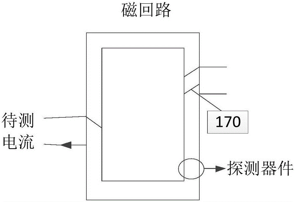
[0013] figure 1 and figure 2 The prior art shown is prone to the stability problem of the output zero point due to both the magnetic material characteristics and the circuit characteristics, that is, the "zero point drift" problem
In practical applications such as the measurement of small currents, this phenomenon has become the fundamental reason for limiting the measurement accuracy of related products

Method used


Image

  • Current measuring method and device
  • Current measuring method and device
  • Current measuring method and device

Examples


Embodiment Construction

[0052] The existing measurement technology is prone to the stability of the output zero point due to the characteristics of magnetic materials and circuit characteristics, that is, the problem of "zero point drift", which affects the measurement accuracy.

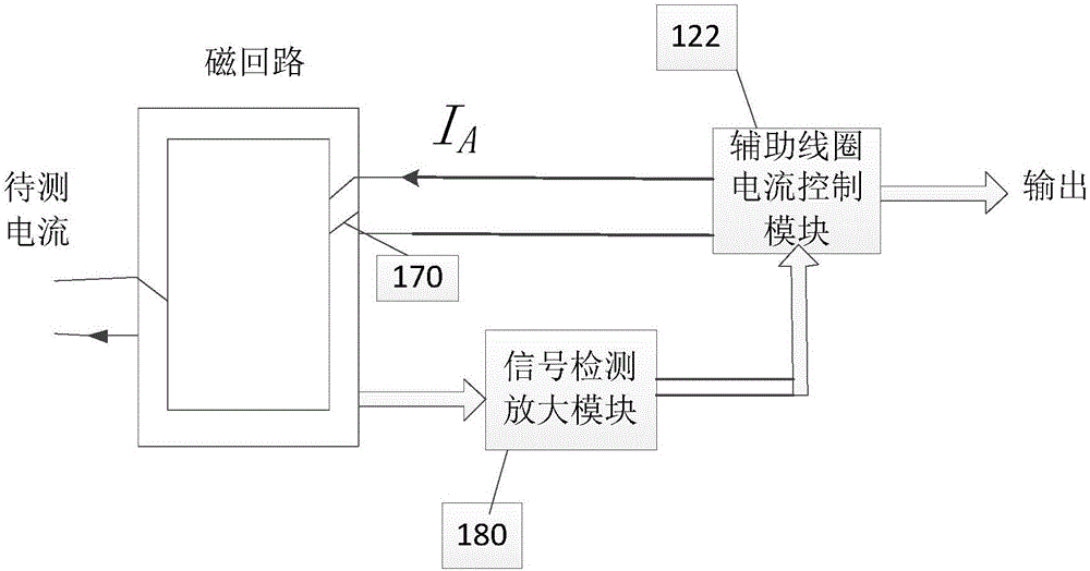
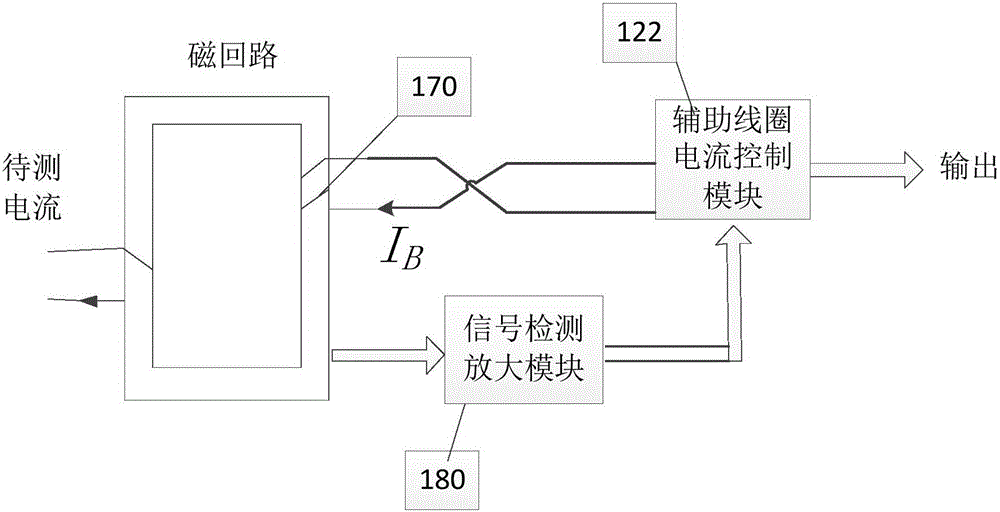
[0053] In view of the above situation, after long-term research and a lot of practice, the researchers provided a current measurement method. On the basis of the existing detection method, it was proposed that by changing the direction of the magnetic field generated by the current in the auxiliary coil in the magnetic circuit, A method for realizing the current signal to be measured in the form of a differential component. Compared with the prior art, the method can greatly reduce the zero point drift of the detection result and improve the measurement accuracy.

[0054] The following will clearly and completely describe the technical solutions in the embodiments of the present invention with reference to the accompanying ...


PUM


Abstract

The invention provides a current measuring method and a current measuring device, which relate to the field of electronic circuits. The current measuring method comprises the steps of: adjusting a first auxiliary current, so that the sum of intensity of a magnetic field generated by the first auxiliary current flowing through an auxiliary coil of an auxiliary current and intensity of a magnetic field generated by a current to be detected is a first magnetic field intensity; acquiring value of the first auxiliary current; switching on a second auxiliary current, wherein direction of magnetic field intensity generated by the second auxiliary current is opposite to direction of magnetic field intensity generated by the first auxiliary current; adjusting the second auxiliary current, so that the sum of intensity of a magnetic field generated by the secondary auxiliary current flowing through the auxiliary coil of the auxiliary current and intensity of the magnetic field generated by the current to be detected is a second magnetic field intensity, and the first magnetic field intensity and the second magnetic field intensity are identical in magnitude and opposite in direction; acquiring value of the second auxiliary current; and carrying out differential operation on the second auxiliary current and the first auxiliary current, and calculating the current to be detected according to a difference value between the second auxiliary current and the first auxiliary current as well as number of turns of the auxiliary coil. The current measuring method can improve the measurement accuracy.

Description

technical field [0001] The invention relates to the field of electronic circuits, in particular to a current measuring method and device. Background technique [0002] In modern industrial control, instrumentation, power electronic equipment and other systems, the non-contact detection technology of current is an indispensable technology to ensure the safe operation of the system. For example, in the power transmission system, after the system has been running for a long time, due to aging, weather and other reasons, the insulation of the transmission wire will inevitably decline, and the tiny leakage current generated at this time may cause the system to refuse to operate or cause malfunction. It is a huge hidden danger to the safe operation of the system. Existing measurement techniques such as figure 1 and figure 2 as shown, figure 1 Shows the current probe that needs to be constructed for non-contact measurement of current. A current probe includes a magnetic circu...

Claims


Application Information

Patent Timeline
Patent Type & Authority Applications(China)
IPC IPC(8): G01R19/00
Inventor 潘飞蹊罗洪亮
Owner SHENZHEN XINRUIDA ELECTRIC POWER EQUIP
Learn More