Supercharge Your Innovation With Domain-Expert AI Agents!

A method and device for measuring touch response time of capacitive touch screen

A capacitive touch screen and response time technology, applied in the field of capacitive touch screen touch response time measurement, measuring capacitive touch screen touch response time, can solve the problems of high precision, low precision, high cost, etc., and achieve good repeatability and price. Inexpensive and easy to measure effects

Active Publication Date: 2017-10-24
NO 55 INST CHINA ELECTRONIC SCI & TECHNOLOGYGROUP CO LTD
View PDF9 Cites 0 Cited by
  • Summary
  • Abstract
  • Description
  • Claims
  • Application Information

AI Technical Summary

Problems solved by technology

[0004] The object of the present invention is to provide a method and device for measuring the touch response time of a capacitive touch screen, aiming at low cost to achieve Reliable Measurement of Capacitive Touch Screen Touch Response Time

Method used


Image

  • A method and device for measuring touch response time of capacitive touch screen
  • A method and device for measuring touch response time of capacitive touch screen
  • A method and device for measuring touch response time of capacitive touch screen

Examples


Embodiment 1

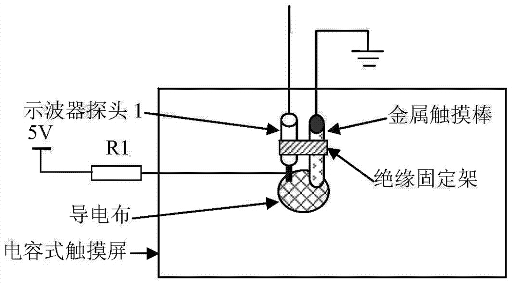
[0045] see figure 1 .

[0046]A device for measuring the touch response time of a capacitive touch screen, consisting of a piece of conductive cloth or other conductive metal film attached to the touch surface of the touch screen, a metal touch rod, a resistor R1, a ground wire of the metal touch rod, and a first measuring probe (such as an oscilloscope probe 1 ), a second measurement probe (such as oscilloscope probe 2), an insulating fixture and a signal acquisition device (such as an oscilloscope). The value of resistor R1 is generally 5kΩ, and can also be other resistance values ​​between 1kΩ and 100kΩ. One end of resistor R1 is connected to the detection end of oscilloscope probe 1, and the other end is connected to a 5V power supply, which can also be a 3.3V, 2.8V power supply, and are not limited to these supply voltages. The metal touch rod is grounded through the ground wire, and fixed together with the oscilloscope probe 1 through the insulating bracket. The test e...

Embodiment 2

[0048] Such as figure 2 , image 3 , Figure 4 with Figure 5 .

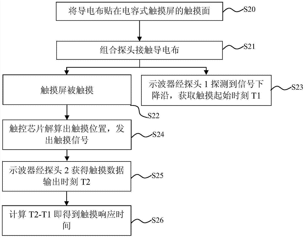
[0049] A method for measuring the touch response time of a capacitive touch screen, it comprises the following steps:

[0050] Step 20, first, paste the conductive cloth on the touch surface of the capacitive touch screen. The conductive cloth is a piece of conductive cloth with adhesive backing or other conductive metal film with a diameter of about 8mm or other shapes with an equal area.

[0051] Step S21, contact the combined probe with the conductive cloth, see image 3 .

[0052] Step S22, the touch screen is touched;

[0053] Step S23, the oscilloscope measures the falling edge of the signal through the probe 1, and obtains the touch start time T1;

[0054] At this time, the metal touch rod in the combination probe causes a touch action, and at the same time, the conductive cloth connects the metal touch rod and oscilloscope probe 1, so that the voltage of oscilloscope probe 1 changes from 5V (or o...


PUM


Abstract

A method and device for measuring the touch response time of a capacitive touch screen. The test device includes a metal touch stick, a conductive cloth, a ground wire, a resistor, an oscilloscope and two oscilloscope probes. Paste the conductive cloth on the surface of the touch screen, connect the metal touch rod to the ground through the wire, connect the oscilloscope probe 1 to the power supply through a resistor, and fix the oscilloscope probe 1 and the metal touch rod together with insulation between the two. The test end of the oscilloscope probe 1 is connected to the metal The touch end surface of the touch stick is flush to form a combined probe, and the oscilloscope probe 2 is connected to the signal output end of the touch screen. When the above-mentioned combined probes are brought into contact with the conductive cloth attached to the surface of the touch screen at the same time, the oscilloscope can detect the touch start time T1 through the oscilloscope probe 1, and then the oscilloscope can detect the time T2 when the touch chip of the touch screen outputs the touch signal through the oscilloscope probe 2, T2 minus T1 is the touch response time. The invention has the characteristics of low cost, accuracy and reliability.

Description

technical field [0001] The invention relates to a touch screen testing technology, in particular to a touch response time measurement technology of a capacitive touch screen, in particular to a method and a device for measuring the touch response time of a capacitive touch screen. Background technique [0002] Capacitive touch screens have been widely used in handheld terminals and various displays, but user experience varies, and touch response time is one of the important performance indicators that affect user experience. Therefore, it is particularly important to measure the touch response time of capacitive touch screens. important. [0003] At present, there are not many testing methods for the response time of the capacitive touch screen, and the key lies in the acquisition of the initial touch moment. One method is to use a metal rod to touch the touch screen first, and then use a wire to ground the metal rod to obtain the touch initiation moment. This method has po...

Claims


Application Information

Patent Timeline
Patent Type & Authority Patents(China)
IPC IPC(8): G01R31/00
Inventor 曹允王光腾李磊王彩玮单寅
Owner NO 55 INST CHINA ELECTRONIC SCI & TECHNOLOGYGROUP CO LTD
Features
  • R&D
  • Intellectual Property
  • Life Sciences
  • Materials
  • Tech Scout
  • Unparalleled Data Quality
  • Higher Quality Content
  • 60% Fewer Hallucinations
Learn More