
Grounding diagnostic method for main loop of locomotive traction converter

A traction converter and a diagnosis method technology are applied in the field of grounding diagnosis of the main circuit of a traction converter of a locomotive, and can solve the problems of low fault diagnosis accuracy and availability, insufficient consideration of abnormal signal acquisition, and inability to perform effective identification. , to reduce the difficulty of troubleshooting, improve accuracy and availability, and reduce misdiagnosis

Inactive Publication Date: 2015-11-18
ZHUZHOU CSR TIMES ELECTRIC CO LTD
View PDF4 Cites 26 Cited by
  • Summary
  • Abstract
  • Description
  • Claims
  • Application Information

AI Technical Summary

Problems solved by technology

[0004] 1) The current diagnostic method usually only considers the grounding situation in the main circuit under ideal conditions, but does not fully consider the judgment of abnormal conditions (such as abnormal signal acquisition, harmonic interference, etc.), so it cannot be used for abnormal conditions. Effective identification may lead to misjudgment;
[0005] 2) The performance of grounding is different under different working conditions. The current diagnosis method can only roughly diagnose the occurrence of grounding faults, but cannot effectively combine the actual working principle of the traction converter to further locate the specific grounding fault position. Accuracy and usability are not high

Method used


Image

  • Grounding diagnostic method for main loop of locomotive traction converter
  • Grounding diagnostic method for main loop of locomotive traction converter
  • Grounding diagnostic method for main loop of locomotive traction converter

Examples


Embodiment Construction

[0033] The present invention will be further described below in conjunction with the accompanying drawings and specific preferred embodiments, but the protection scope of the present invention is not limited thereby.

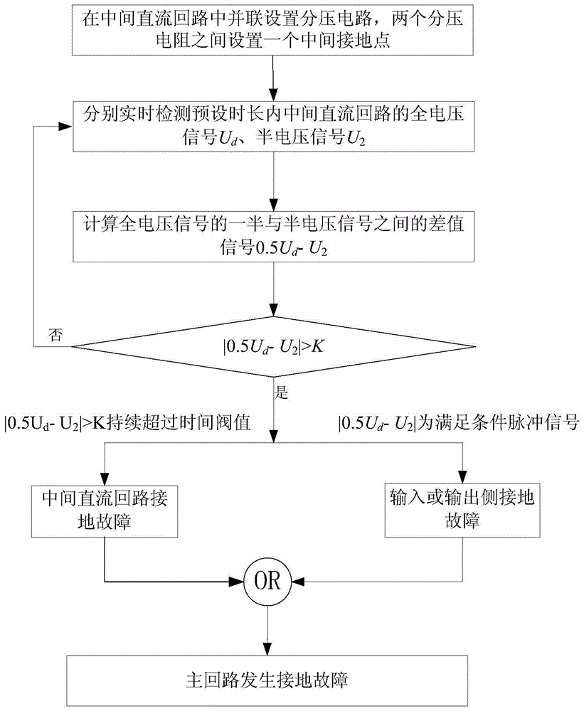
[0034] Such as figure 1 As shown, the method for diagnosing grounding of the main circuit of the locomotive traction converter in this embodiment, the steps include:

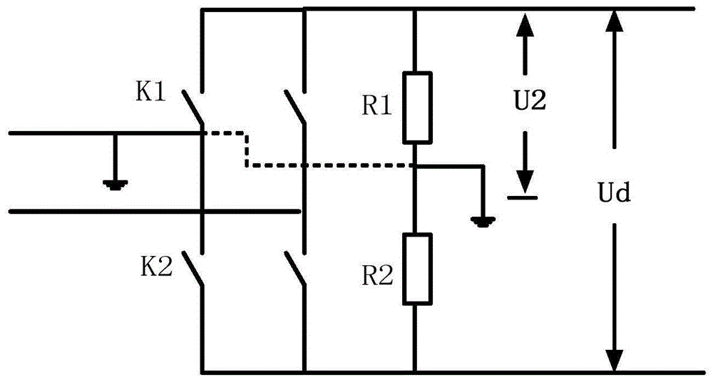
[0035] 1) A voltage divider circuit is set in parallel in the intermediate DC circuit of the target traction converter. The voltage divider circuit is composed of two voltage divider resistors with the same resistance in series, and an intermediate indirect point is set between the two voltage divider resistors; Detecting the voltage signals at both ends of the intermediate DC circuit and the voltage signal between both ends of the intermediate DC circuit and the intermediate point within a preset time period, and obtaining the full voltage signal U d and the half-voltage signal U 2 output;

[...


PUM


Abstract

The invention discloses a grounding diagnostic method for a main loop of a locomotive traction converter. The grounding diagnostic method comprises the steps of: 1) arranging a voltage dividing circuit in an intermediate DC loop of a target traction converter in parallel, detecting voltage signals at two ends of the intermediate DC loop and voltage signals between a neutral grounding point and two ends of the intermediate DC loop within a preset duration in real time to obtain a full voltage signal and a half voltage signal for output; 2) calculating a difference value signal between the full voltage signal and the half voltage signal, diagnosing whether a main loop of the target traction converter has a grounding fault according to a value of the difference value signal, and executing the step 3 when the occurrence of the grounding fault is diagnosed; 3) and determining the type of the grounding fault according to the changing trend of the difference value signal within the preset duration. The grounding diagnostic method for the main loop of the locomotive traction converter has the advantages of being simple in implementation, high in grounding fault diagnostic efficiency and accuracy, and capable of achieving determination of the specific type of the grounding fault.

Description

technical field [0001] The invention relates to the technical field of electric locomotive fault detection, in particular to a grounding diagnosis method for a main circuit of a traction converter of an electric locomotive. Background technique [0002] The electric transmission system of electric locomotive has the characteristics of high voltage and high current, so ensuring the normal operation of the transmission system is the prerequisite for ensuring the reliable operation of the locomotive. During the operation of the locomotive, the main circuit may be grounded due to cable aging, vibration and friction, etc. Although usually one point of grounding will not have a great impact on the normal operation of the system, when there are two or more points of grounding, it may A large short-circuit current is generated, which causes burning of the components of the electric transmission system of the locomotive, and even causes the locomotive to break in severe cases. There...

Claims


Application Information

Patent Timeline
IPC IPC(8): G01R31/02
Inventor 成正林高首聪蒋奉兵刘良杰徐绍龙李学明黄明明彭辉袁靖廖亮
Owner ZHUZHOU CSR TIMES ELECTRIC CO LTD
Learn More