
An elevation angle adjustment structure of a vehicle antenna

A vehicle-mounted antenna and elevation angle adjustment technology, applied to antennas, antennas suitable for movable objects, electrical components, etc., can solve the problems that the antenna cannot be aimed at the satellite direction, the signal of the vehicle-mounted communication equipment is weak, and the motor power is not very large. , to achieve the effect of stable signal, good stability and high precision

Active Publication Date: 2018-08-10
ZHEJIANG CHINASTAR ELECTRONICS SCI & TECH
View PDF4 Cites 0 Cited by
  • Summary
  • Abstract
  • Description
  • Claims
  • Application Information

AI Technical Summary

Problems solved by technology

For the vehicle-mounted satellite antenna, the power of the motor used is not very large. In the case of strong vibration during driving, the belt drive is prone to the situation that the antenna elevation angle cannot be adjusted due to insufficient strength, that is, the antenna cannot be aligned with the direction of the satellite. As a result, the signal received by the vehicle communication equipment is weak, and even the signal cannot be received normally

Method used


Image

  • An elevation angle adjustment structure of a vehicle antenna
  • An elevation angle adjustment structure of a vehicle antenna
  • An elevation angle adjustment structure of a vehicle antenna

Examples


Embodiment 1

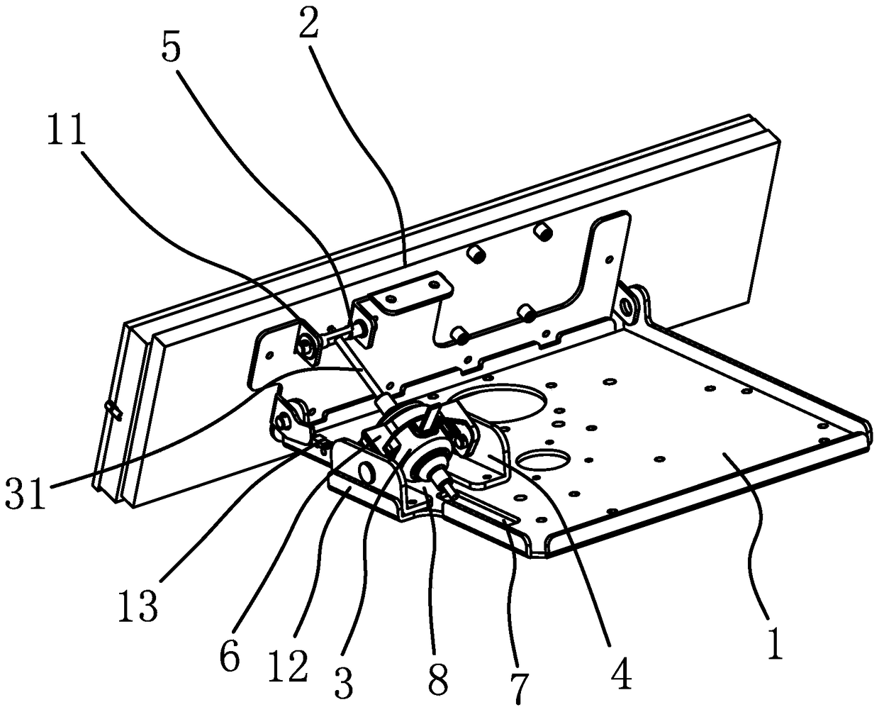
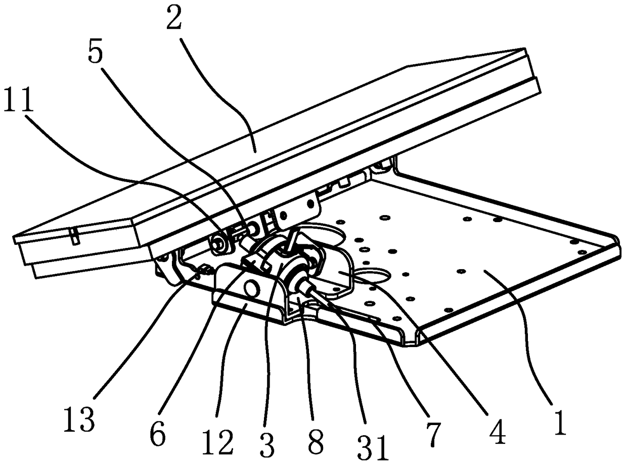
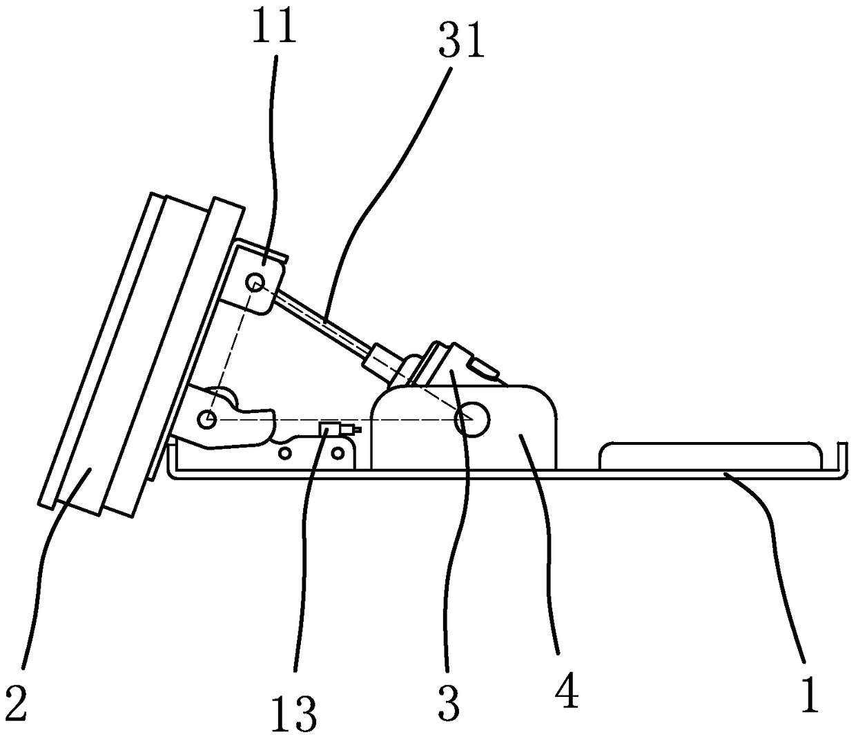
[0029] like figure 1 , figure 2 As shown, the vehicle-mounted antenna includes a base plate 1, a rotating plate 2, a push rod motor 3, an articulating frame 4, a rotating shaft 5 and a sensor 13.

[0030] The bottom plate 1 can be rotated 360 degrees and installed on the top of the mounting plate (not shown in the figure). There is a gap between the bottom plate 1 and the mounting plate. An antenna is installed on the rotating plate 2. The rotating plate 2 can rotate around the hinge point of the base plate 1 and the rotating plate 2 .

[0031] The elevation angle adjustment structure comprises a push rod motor 3, and the push rod motor 3 comprises a push rod 31. The firmware is fixedly connected with the bottom plate 1, and there is a rubber cushion between the hinged frame 4 and the bottom plate 1, and the hinged frame 4 leans against the positioning piece 12, and there is a notch 8 at the center of the bottom of the hinged frame 4, and the notch 8 is located on the push ...

Embodiment 2

[0039] like Figure 6 As shown, the structure and principle of Embodiment 1 in this embodiment are basically the same, the difference is that in this embodiment, there is a rotating hole in the rotating shaft 5, and the top end of the push rod 31 is set in the rotating hole, and the push rod 31 The outer diameter of the push rod 31 is slightly smaller than the inner diameter of the rotating hole. A pair of limit nuts 10 are fixedly connected to the top of the push rod 31. Spring washers are arranged between them, and a pair of limit nuts 10 make the push rod 31 and the rotating shaft 5 axially positioned.


PUM


Abstract

The invention provides an elevation angle adjusting structure of a vehicle-borne antenna, belongs to the technical field of automobile parts, and helps to solve the problems that a conventional vehicle-borne antenna is low in elevation angle adjusting precision and poor in signal reception stability. The vehicle-borne antenna comprises a base plate and a rotating plate for installation of the antenna. The rotating plate and the base plate are hinged to each other. The rotating plate can rotate about the hinge point of the base plate and the rotating plate. The elevation angle adjusting structure includes a push rod motor. The push rod motor includes a push rod. The push rod can axially move along the push rod motor. A hinge support is arranged on the base plate. The push rod motor is hinged to the hinge support, and can rotate about the hinge point of the push rod motor and the hinge support. The rotating plate is hinged to a rotating shaft, the top end of the push rod penetrates and is axially positioned in the rotating shaft, and the push rod can rotate relative to the rotating shaft. The elevation angle adjusting structure has the advantage that the signal reception stability of the vehicle-borne antenna can be improved.

Description

technical field [0001] The invention belongs to the technical field of auto parts, and relates to an elevation angle adjustment structure of a vehicle antenna. Background technique [0002] With the development and accessibility of vehicles such as automobiles, people's requirements for the comfort, safety, convenience and intelligence of vehicles are increasing. In order to meet people's requirements for the use of vehicles, many vehicle-mounted devices have emerged, including vehicle-mounted communication devices, and vehicle-mounted antennas are installed outside the vehicle to receive or transmit signals. [0003] At present, the vehicle-mounted satellite antenna mainly has the following characteristics: In order to continuously receive satellite signals and ensure that the antenna surface is always aligned with the satellite direction, the motor is driven by a belt to drive the panel to rotate to adjust the angle of elevation or azimuth. For the vehicle-mounted satelli...

Claims


Application Information

Patent Timeline
Patent Type & Authority Patents(China)
IPC IPC(8): H01Q3/06H01Q1/32
Inventor 夏林多郑伟军杨彪蔡瑶瑶
Owner ZHEJIANG CHINASTAR ELECTRONICS SCI & TECH
Learn More