
Low-voltage power distribution cabinet for power system

A technology for power systems and power distribution cabinets, which is applied in the field of low-voltage power distribution cabinets and equipment for power systems. It can solve problems such as inability to achieve effective heat dissipation, high temperature in power distribution cabinets, and deformation of power distribution cabinets. It achieves reliable design principles, Effect of reducing noise and ensuring accuracy

Active Publication Date: 2015-11-18
国网山东博兴县供电公司
View PDF8 Cites 19 Cited by
  • Summary
  • Abstract
  • Description
  • Claims
  • Application Information

AI Technical Summary

Problems solved by technology

When the components in the power distribution cabinet are working, they will generate a lot of heat, which cannot achieve effective heat dissipation.
[0005] In addition, when a short-circuit arcing fault occurs in the low-voltage power distribution cabinet, high temperature and high pressure will be generated instantly in the power distribution cabinet; if the protection level of the power distribution cabinet is high, the pressure cannot be released smoothly outside the cabinet, which may cause The distribution cabinet body is permanently deformed, and even the cabinet door is blown away. There is no special pressure relief device in the general low-voltage distribution cabinet, so there will be a large safety hazard during operation.

Method used


Image

  • Low-voltage power distribution cabinet for power system
  • Low-voltage power distribution cabinet for power system
  • Low-voltage power distribution cabinet for power system

Examples


Embodiment Construction

[0025] The present invention will be described in detail below with reference to the accompanying drawings and specific embodiments. The following embodiments are explanations of the present invention, but the present invention is not limited to the following embodiments.

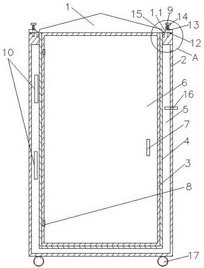
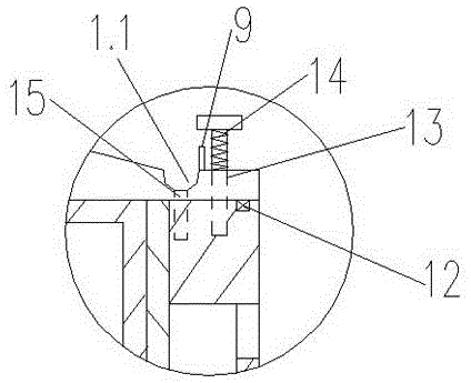
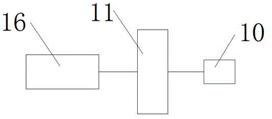
[0026] like Figures 1 to 3 As shown, a low-voltage power distribution cabinet used in a power system provided by the present invention includes a cabinet body, and the cabinet body includes a top cover 1, a side wall, a cabinet door 6 and a base, and the side walls and the base include an outer plate 2 and an inner plate 3, the inner plate 3 is provided with an insulating plate 4, a cooling interlayer 5 is arranged between the insulating plate 4 and the outer plate 2, a cooling liquid is arranged in the cooling interlayer 5, and the top The cover 1 and the outer plate 2 are connected by a screw 13, the upper part of the screw 13 is a polished rod, and the lower part is provided with threads, the lower part...


PUM

PropertyMeasurementUnit
Thicknessaaaaaaaaaa
Thicknessaaaaaaaaaa

Abstract

The invention relates to a low-voltage power distribution cabinet for a power system. The low-voltage power distribution cabinet comprises a cabinet body, wherein the cabinet body comprises a top cover, a side wall, a cabinet door and a base, the low-voltage power distribution cabinet is characterized in that the side wall and the base both comprise an outer plate and an inner plate, an insulation plate is arranged outside the inner plate, a cooling sandwiched layer is arranged between the insulation plate and the outer plate, a cooling liquid is arranged in the cooling sandwiched layer, the top cover and the outer plate are connected via a screw rod, the upper part of the screw rod is provided with an optical rod, the lower part of the screw rod is provided with a thread and is in threaded connection with the outer plate, a spring sleeves the optical rod, the top cover can vertically move along the optical rod, a water storage groove is arranged on the top cover, a water baffle plate is arranged at the edge of a low end of the water storage groove, the water storage groove is connected with a water guide pipe, a temperature sensor and semiconductor refrigeration chips are further arranged in the cooling sandwiched layer, the temperature sensor is connected with a micro controller, and the micro controller is connected to power supply ends of the semiconductor chips.

Description

technical field [0001] The invention belongs to the technical field of electric power equipment, and relates to equipment for power systems, in particular to a low-voltage power distribution cabinet used in power systems; the low-voltage power distribution cabinet can not only effectively prevent rainwater from entering the cabinet, but also effectively dissipate heat and pressure relief to ensure the safe use of low-voltage power distribution cabinets. Background technique [0002] As the power distribution equipment in the power system, the low-voltage power distribution cabinet is very important in the entire power grid transmission process. [0003] The low-voltage power distribution cabinet is usually installed outdoors, and its structural encapsulation is poor, so it cannot be used for outdoor installation, which limits the scope of use of low-voltage power distribution equipment. When encountering rainy weather, due to poor structural encapsulation, rainwater will en...

Claims


Application Information

Patent Timeline
IPC IPC(8): H02B1/56H02B13/025H02B1/28
Inventor 刘志孙海辉李娟张肖肖
Owner 国网山东博兴县供电公司
Learn More