Integrated type permanent magnet synchronous motor shell

A permanent magnet synchronous motor, an integrated technology, applied in the direction of synchronous machine parts, casing/cover/support, electrical components, etc., can solve the problems of complex production process, high production cost, poor heat dissipation effect, etc., and achieve failure The effect of low efficiency, low production cost and reliable connection

Active Publication Date: 2015-11-18
浙江双菱新能源科技有限公司
View PDF7 Cites 2 Cited by
  • Summary
  • Abstract
  • Description
  • Claims
  • Application Information

AI Technical Summary

Problems solved by technology

[0002] With the rapid development of electric vehicle buses, the number of motors used in automobiles has also increased. The motors used in automobile buses are generally 100kw, and the peak value is about 200kw. The key to motors used in buses. At present, the cooling methods of motors include fan cooling, spiral water channel cooling or water jacket cooling. Most of the spiral water channels or water jackets are welded on the outer surface of the motor shell to connect the spiral water channels or water jackets. The disadvantage is that the production process is complicated, the production cost is high, the failure rate is high, and the heat dissipation effect is poor

Method used


Image

  • Integrated type permanent magnet synchronous motor shell
  • Integrated type permanent magnet synchronous motor shell
  • Integrated type permanent magnet synchronous motor shell

Examples


Embodiment Construction

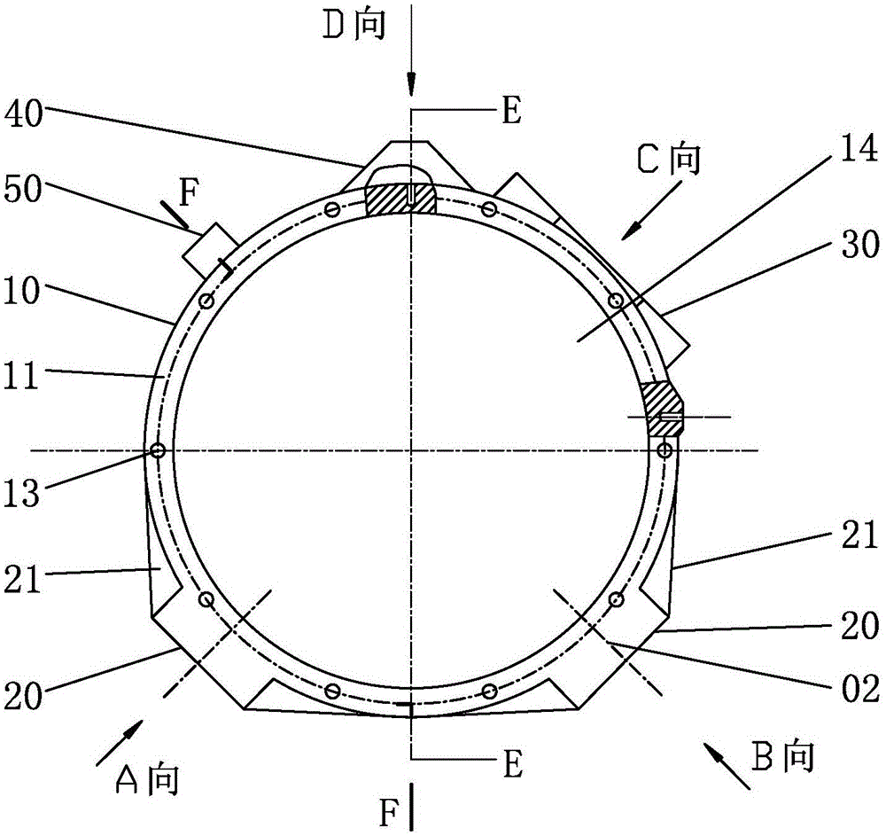
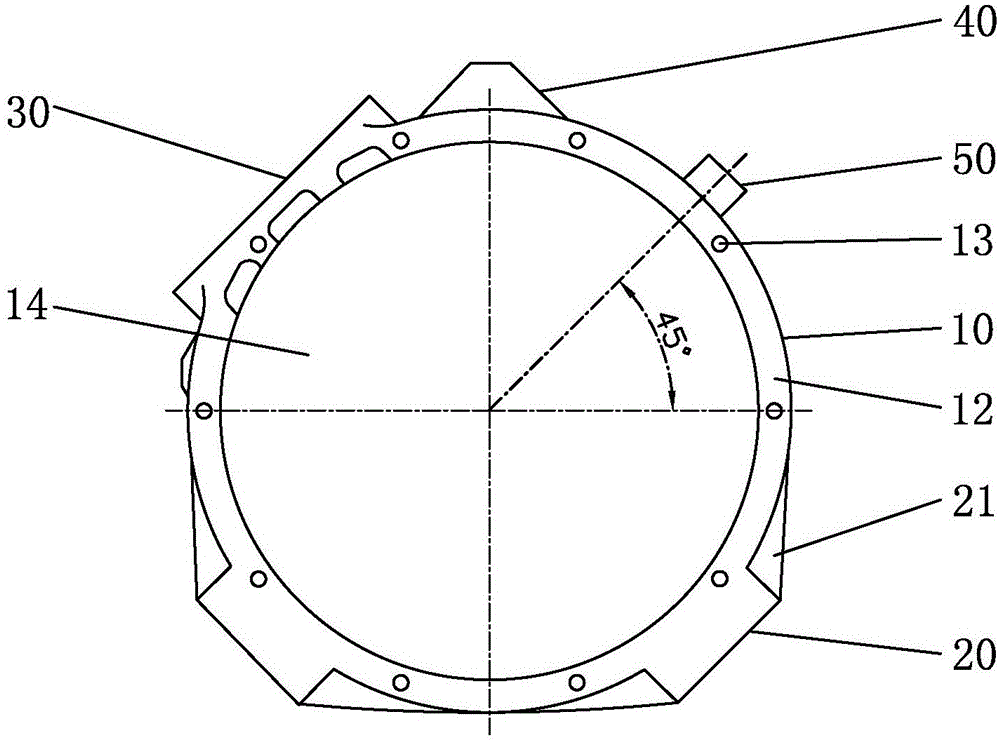
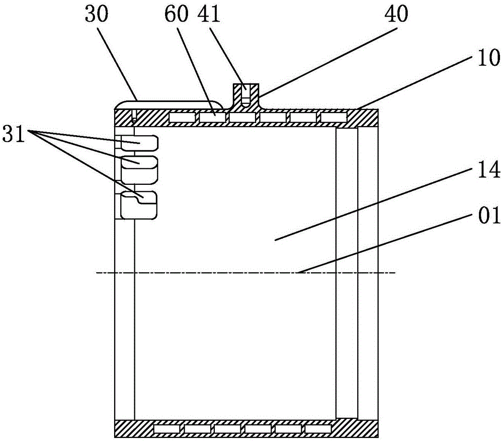
[0026] The present invention will be further described below with specific embodiments in conjunction with the drawings, see figure 1 — Picture 9 :

[0027] One-piece permanent magnet synchronous motor housing. The side wall 10 of the cylinder with a cylindrical center hole 14 has a spiral heat dissipation channel 60 integrally formed with the cylinder, and a junction box is integrally formed with the cylinder on the outer wall of the cylinder. 30. Lifting ears 40 and at least three circumferentially spaced convex strips 50 with the axis in the up and down direction. The inlet and outlet ports 62 at the upper and lower ends of the spiral heat dissipation channel 60 pass through the side wall 10 of the cylinder and are located on the left side of the junction box 30. The upper and lower parts of the strip 50 and the upper and lower sides of the other two protruding strips 50 are provided with mounting seats 20. Each mounting seat 20 is provided with two or more threaded blind hol...


PUM


Abstract

The invention belongs to the motor shell technical field and relates to an integrated type permanent magnet synchronous motor shell. A spiral heat dissipation water channel is formed in the side wall of a cylinder with a cylindrical central hole, wherein the spiral heat dissipation water channel and the cylinder are molded integrally; the outer wall of the cylinder is provided with a junction box, a hanging lug and at least three circumferentially-arranged protruding bars of which the axes are arranged along a vertical direction, wherein the junction box, the hanging lug, the protruding bars and the cylinder are molded integrally; a water inlet and a water outlet at the upper end and the lower end of the spiral heat dissipation water channel pass through the side wall of the cylinder and are located at the upper part and the lower part of the protruding bar at the left side of the junction box; the upper sides and the lower sides of the other two protruding bars are respectively provided with an installation seat; more than two threaded blind holes are formed in each installation seat; each installation seat is provided with more than two transverse reinforcing ribs; threaded blind holes are circumferentially formed at two end surface of the cylinder at intervals; wire through holes which pass through the side wall of the cylinder are formed in the side wall of the cylinder and are located inside the junction box; and the junction box and the three protruding bars are separated out from each other by 90 degrees. The integrated type permanent magnet synchronous motor shell has the advantages of excellent heat conduction and heat dissipation performance, structural simplicity, practicability, low failure rate and low production cost, and can be suitable for high-power permanent magnet synchronous motors.

Description

Technical field [0001] The invention belongs to the technical field of motor casings, and particularly refers to an integrated permanent magnet synchronous motor casing. Background technique [0002] With the rapid development of electric vehicle buses, the number of automotive motors has also increased. The motors for automotive buses are generally 100kw, with a peak value of about 200kw. Due to the high power of the motor, the heat generated is also large, and good heat dissipation becomes a car. The key to the motor for buses, the current cooling methods of the motor include fan cooling, spiral water channel cooling or water jacket cooling. The spiral water channel or water jacket is mostly welded to the outer surface of the motor shell to connect the spiral water channel or water jacket. The disadvantage is that the production process is complicated, the production cost is high, the failure rate is high, and the heat dissipation effect is poor. Summary of the invention [000...

Claims


Application Information

Patent Timeline
Patent Type & Authority Applications(China)
IPC IPC(8): H02K21/02H02K5/20H02K5/04
Inventor 张良应有成祝福俊黄小芳
Owner 浙江双菱新能源科技有限公司
Why Eureka
Try Eureka