
Inductance coil end removal equipment and utilization method thereof

A technology of inductance wire and equipment, which is applied in the field of inductance wire tail removal equipment, can solve the problems of low processing accuracy, longer time consumption, and high labor cost, so as to improve product qualification rate and processing accuracy, avoid product defects, and save labor costs Effect

Active Publication Date: 2015-11-25
广东昭信平洲电子有限公司
View PDF9 Cites 0 Cited by
  • Summary
  • Abstract
  • Description
  • Claims
  • Application Information

AI Technical Summary

Problems solved by technology

At present, manual cutting is usually used to remove the tail of the inductor, which takes a long time, has low production efficiency, and high labor costs.
Especially for inductors using micro-coils, such as ZJY series inductors; due to small size and high precision requirements, it will take longer to remove the inductor tail; at the same time, the individual differences and proficiency of the production personnel have an impact on the accuracy of the removal of the inductor tail. If the removal length is too short and the inductance terminals are cut, etc., the unqualified inductances account for about 2% of the total production.
Therefore, in addition to low production efficiency and high labor costs, the current method of removing inductor wire tails also has shortcomings such as low processing accuracy and waste of materials.

Method used


Image

  • Inductance coil end removal equipment and utilization method thereof
  • Inductance coil end removal equipment and utilization method thereof
  • Inductance coil end removal equipment and utilization method thereof

Examples


Embodiment 1

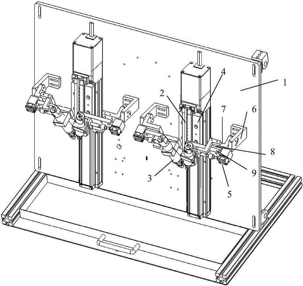
[0039] This embodiment describes a device for removing inductance wire tails, which can be used to automatically remove inductance wire tails of ZJY series inductors and the like. The structure of the inductance line tail removal equipment is as follows: Figure 1 to Figure 5 Shown; Inductance wire tail removal equipment includes a control device, a frame 1, a jig 2, a shearing device 3, a shearing bracket 7, a fixed seat 6, a slide table 8 and a slider 9.

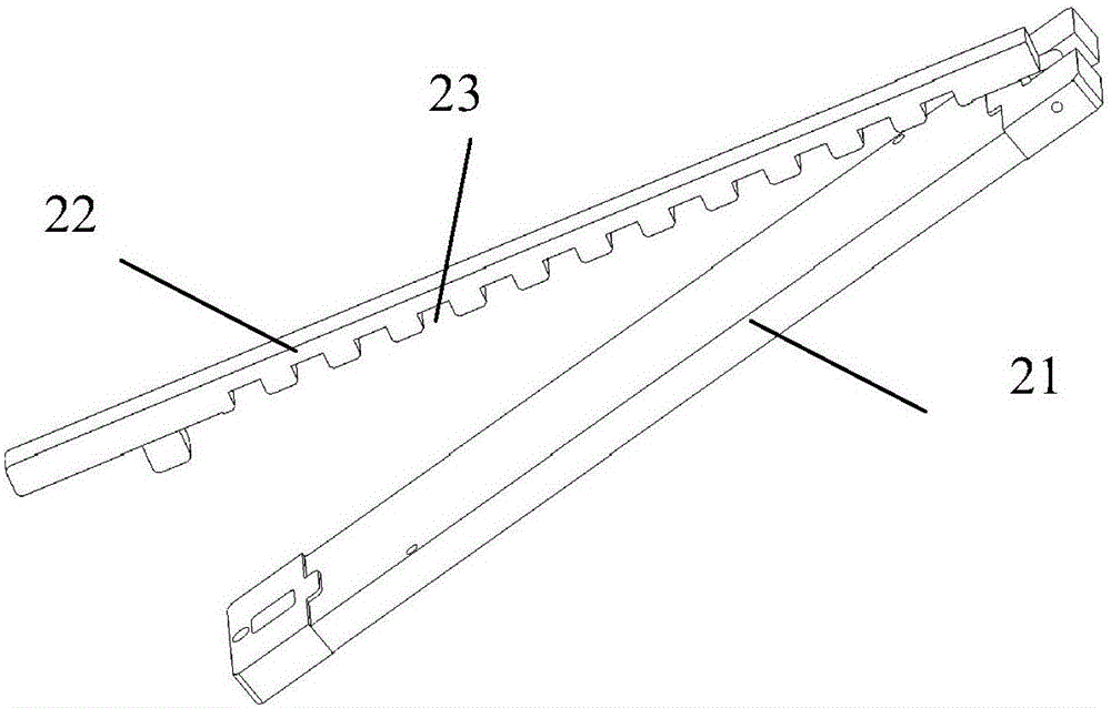
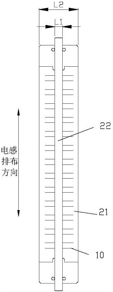
[0040] Wherein, the jig 2 includes a jig base 21 and a cover rod 22 hinged with the jig base 21 and covered on the jig base 21, the jig base 21 and the cover rod 22 form a clamping structure together; the jig base 21 and A positioning piece is provided between the cover rods 22 to realize the fixation between the jig base 21 and the cover rod 22 . The cover rod 22 is provided with a plurality of grooves 23 arranged side by side for clamping the coil; the width L1 of the cover rod

Embodiment 2

[0051] This embodiment describes a device for removing the tail of an inductor, which includes a frame, a control device, a jig for positioning the inductor, and a cutting device for cutting the tail of the inductor; the cutting device is formed to be used with the tail of the inductor Position relative clipping regions. The jig is connected to the frame; the shearing device is connected to the frame through the first driving device and the second driving device, so as to respectively realize the movement of the shearing device along the direction of inductance arrangement and the movement toward or away from the end of the inductance line; the drive The first device, the second driving device and the shearing device are respectively connected with the control device for signals.

[0052] When working, first move the shearing device along the direction of inductance arrangement, so that the tail of the inductance line is opposite to the cutting area of ​​the shearing device; t...

Embodiment 3

[0056] This embodiment describes a device for removing the tail of an inductor, which includes a frame, a control device, a jig for positioning the inductor, and a cutting device for cutting the tail of the inductor; the cutting device is formed to be used with the tail of the inductor Position relative clipping regions. The jig is connected to the frame through the drive device 1 to realize the movement of the jig along the direction of the inductance arrangement; the shearing device is connected to the frame through the drive device 2 and the drive device 3 to respectively realize the movement of the shearing device along the direction of the inductance arrangement. And the shearing device moves toward or away from the tail of the inductor.

[0057] When working, first move the shearing device and the jig towards each other along the direction of inductance arrangement, so that the tail of the inductance line is opposite to the shearing area of ​​the shearing device, which c...


PUM


Abstract

The invention provides inductance coil end removal equipment. The inductance coil end removal equipment is characterized by comprising a rack, a control device, a jig and a shearing device, wherein a shearing area opposite to the position of an inductance coil end is formed on the shearing device; the jig and the shearing device are arranged in one of the following three ways: (1) the jig is connected with the rack through a drive device I, and the shearing device is connected with the rack through a drive device II; (2), the jig is connected with the rack, the shearing device is connected with the rack through the drive device I and the drive device II; (3), the jig is connected with the rack through the drive device I, and the shearing device is connected with the rack through the drive device II and a drive device III. The inductance coil end removal equipment can be started before the inductance coil end and the equipment are fixed or positioned, manual operation is reduced, work time is saved, and the production efficiency and the processing precision are improved. The invention further provides a utilization method of the inductance coil end removal equipment which can reduce the labor intensity and improve the production efficiency.

Description

technical field [0001] The invention relates to the technical field of inductance manufacturing, and more specifically relates to an inductance line tail removal device and a method for using the same. Background technique [0002] In the manufacturing process of the inductor, the coil needs to be placed on the coil board, and the coil wire is fixed on the coil board; after the coil wire is fixed, the end of the coil wire is usually left with an excessively long part to form the inductor wire tail. At present, manual cutting is usually used to remove the inductor wire tail, which takes a long time, has low production efficiency and high labor cost. Especially for inductors using miniature coils, such as ZJY series inductors; due to the small size and high precision requirements, it will take longer to remove the tails of the inductors; at the same time, the individual differences and proficiency of the production personnel have an impact on the accuracy of the removal of the...

Claims


Application Information

Patent Timeline
Patent Type & Authority Applications(China)
IPC IPC(8): B21F11/00H01F41/04
Inventor 宋鹏李培涛周筱晶李锦松
Owner 广东昭信平洲电子有限公司
Learn More