Droplet microoperation mechanical hand structure and posture controlling method thereof

A technology of micro-manipulation and manipulators, applied in manipulators, program-controlled manipulators, manufacturing tools, etc., can solve the problems of complex application environment, difficult processing, and mutual disturbance of motion, so as to achieve precise control and control methods and reduce processing difficulty , a wide range of effects

Active Publication Date: 2015-11-25
SOUTH CHINA UNIV OF TECH
View PDF6 Cites 6 Cited by
  • Summary
  • Abstract
  • Description
  • Claims
  • Application Information

AI Technical Summary

Problems solved by technology

In addition to the above methods, micro-robots are increasingly used in micro-assembly, but due to the complexity of the system and the limitations of the application environment, it has not been widely used.
On the basis of previous studies, the research team proposed a multi-rod droplet micromanipulator in a patent for a liquid droplet micromanipulator and its control method. This patent can change the attitude of tiny objects, but There ...

Method used


Image

  • Droplet microoperation mechanical hand structure and posture controlling method thereof
  • Droplet microoperation mechanical hand structure and posture controlling method thereof
  • Droplet microoperation mechanical hand structure and posture controlling method thereof

Examples


Embodiment 1

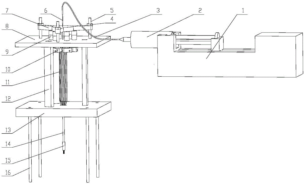
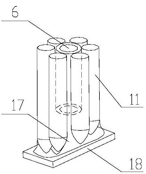
[0043] like Figure 1 to Figure 7 As shown, a droplet micro-manipulator structure includes an injection assembly, a control assembly, a fixed bracket assembly, a drive assembly arranged on the fixed bracket assembly, and an execution assembly connected to the drive assembly and the injection assembly. The injection assembly includes a syringe 2, a propeller 1 for driving the syringe 2, and a hose 3 connected to the liquid outlet of the syringe 2; The motor positioning plate 8 above the lower fixed plate 13, the thrust plate 7 connected above the motor positioning plate 8 by bolts 5 and nuts; The micromotor 9 in the stepped through hole of the motor positioning plate 8, the tops of the six micromotors 9 are suppressed by the thrust plate 7, and a transmission connecting plate is provided directly below the output shaft of each of the micromotors 9 10. There is a certain gap between each transmission connecting plate 10 (see Figure 5 , Image 6 ), the transmission connecting...

Embodiment 2

[0049] A method for attitude control of a droplet micro-manipulator structure, using the droplet micro-manipulator structure described in Embodiment 1, comprising the steps of:

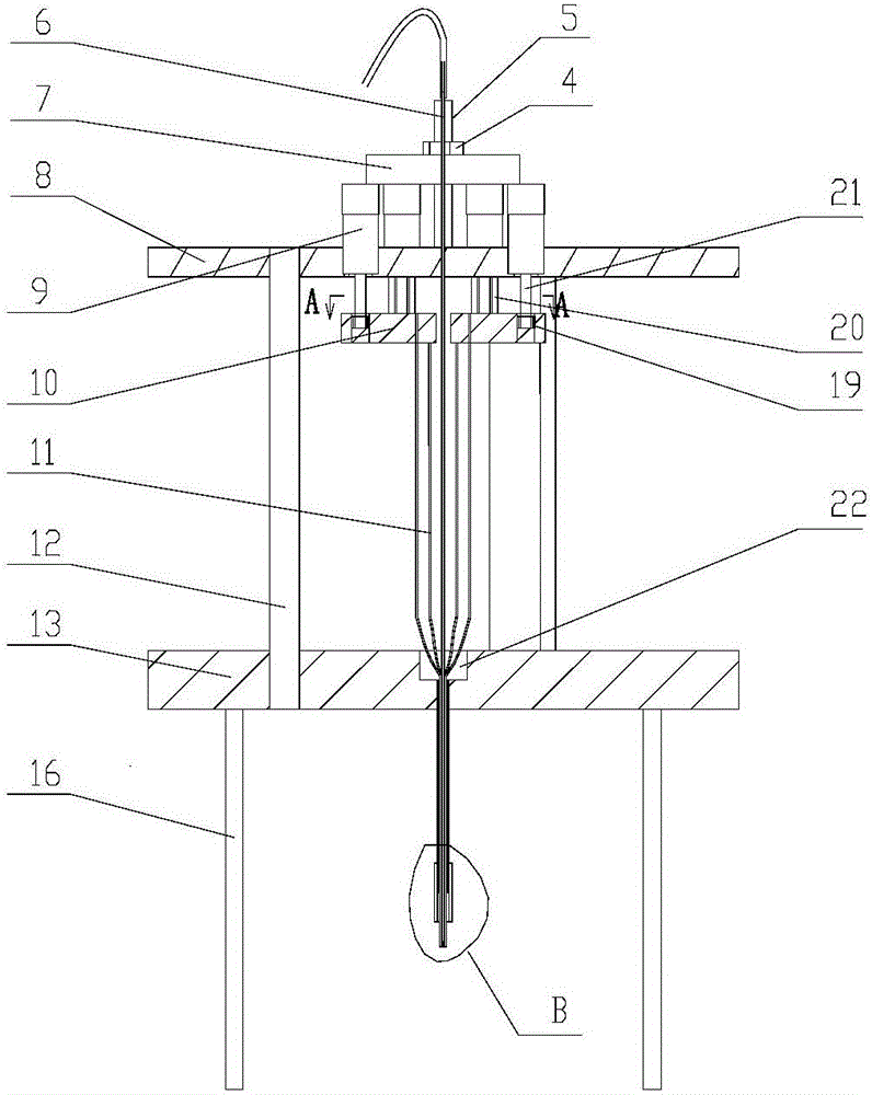
[0050] 1) The droplet adsorbs the tiny parts 18, and injects liquid into the capillary microtube 6 through the syringe to form a droplet 17 on the tip of the tungsten wire rod. The amount of the injected droplet is about 10 μl. When contacting the tiny component 18, the tiny component 18 is absorbed in the tungsten wire rod 11 lower end and is in a horizontal state. At this moment, a liquid bridge system is formed between the tiny component 18, the liquid drop and the tungsten wire rod (see figure 2 ), this step injects a certain amount of liquid into the capillary microtube through the injection device, forms tiny liquid droplets at the bottom of the tungsten wire rod, and controls the movement of the tungsten wire rod to approach the small parts to absorb the small parts;

[0051] 2) Adjust the pos...

Embodiment 3

[0057] A method for attitude control of a droplet micro-manipulator structure, comprising steps:

[0058]1) The droplet adsorbs the tiny parts 18, and injects liquid into the capillary microtube 6 through the syringe to form a droplet 17 on the tip of the tungsten wire rod. The amount of the injected droplet is about 10 μl. When contacting the tiny component 18, the tiny component 18 is absorbed in the tungsten wire rod 11 lower end and is in a horizontal state. At this moment, a liquid bridge system is formed between the tiny component 18, the liquid drop and the tungsten wire rod (see figure 2 ), this step injects a certain amount of liquid into the capillary microtube through the injection device, forms tiny liquid droplets at the bottom of the tungsten wire rod, and controls the movement of the tungsten wire rod to approach the small parts to absorb the small parts;

[0059] 2) Adjust the posture of the micro-component 18 according to the preset target posture, and the co...


PUM

PropertyMeasurementUnit
The inside diameter ofaaaaaaaaaa
Depthaaaaaaaaaa

Abstract

The invention provides a droplet microoperation mechanical hand structure. The droplet microoperation mechanical hand structure comprises an injection component, a control component, a fixing bracket component, a driving component arranged on the fixing bracket component, and an executive component connected with the driving component and the injection component. The invention also provides a posture controlling method of the droplet microoperation mechanical hand structure. According to the posture controlling method, the up and down movement amount, movement order and position of a constrained point of all tungsten filament bars are controlled, so that the postures of tiny parts adsorbed on droplets based on the surface tension are changed, and the accurate control of the postures of the tiny parts is achieved; compared with the prior art, the posture controlling method has the advantages of being more stable and more accurate in posture control, being easy and feasible, and being applicable to nondestructive operation of tiny objects with arbitrary shapes.

Description

technical field [0001] The present invention relates to the technical field of droplet micro-manipulation, in particular to a structure of a liquid-drop micro-manipulation manipulator and a method for controlling its attitude. Background technique [0002] With the miniaturization of mechanical and electronic products, the components of mechanical and electrical products are also gradually miniaturized and thinned. In the assembly of micro components, the assembly precision requirements are getting higher and higher, which often involves the position and posture of micro components. Adjustment and non-destructive operation, which place high demands on micromanipulation devices. At present, for the operation and assembly of tiny components at home and abroad, there are mainly methods based on micro-gripper tools, vacuum adsorption methods, and surface tension methods. In terms of micro grippers, for example, TAMIO of Nagoya University in Japan has developed a two-finger micr...

Claims


Application Information

Patent Timeline
IPC IPC(8): B25J9/08B25J9/18B25J9/00
CPCB25J9/08
Inventor 张勤甘裕明于腾青山尚之
Owner SOUTH CHINA UNIV OF TECH
Why Eureka
Try Eureka