A attitude control method for a liquid droplet micromanipulator structure
A posture control and manipulator technology, applied in the direction of manipulators, program control manipulators, manufacturing tools, etc., can solve the problems of complex application environment, difficult processing, mutual disturbance of motion, etc., to achieve precise control control methods and reduce processing difficulty , a wide range of effects
- Summary
- Abstract
- Description
- Claims
- Application Information
AI Technical Summary
Problems solved by technology
Method used
Image
Examples
Embodiment 1
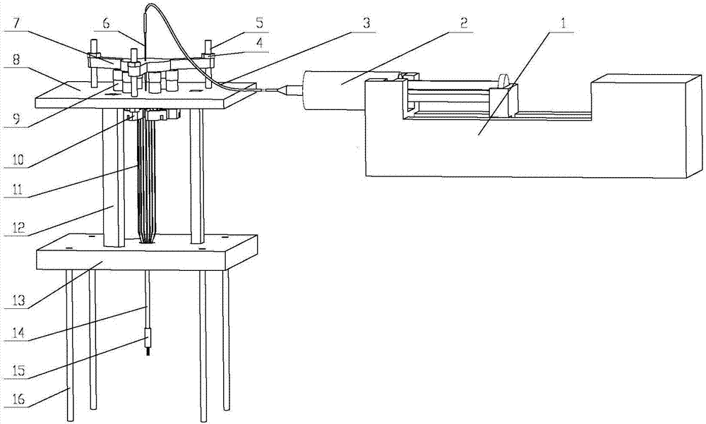
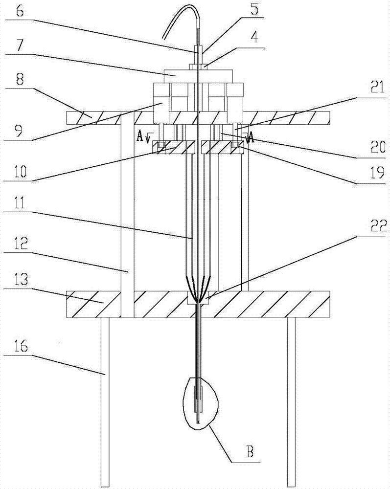
[0043] like Figure 1 to Figure 7 As shown, a droplet micro-manipulator structure includes an injection assembly, a control assembly, a fixed bracket assembly, a drive assembly arranged on the fixed bracket assembly, and an execution assembly connected to the drive assembly and the injection assembly. The injection assembly includes a syringe 2, a propeller 1 for driving the syringe 2, and a hose 3 connected to the liquid outlet of the syringe 2; The motor positioning plate 8 above the lower fixed plate 13, the thrust plate 7 connected above the motor positioning plate 8 by bolts 5 and nuts; The micromotor 9 in the stepped through hole of the motor positioning plate 8, the tops of the six micromotors 9 are suppressed by the thrust plate 7, and a transmission connecting plate is provided directly below the output shaft of each of the micromotors 9 10. There is a certain gap between each transmission connecting plate 10 (see Figure 5 , Image 6 ), the transmission connecting...
Embodiment 2
[0049] A method for attitude control of a droplet micro-manipulator structure, using the droplet micro-manipulator structure described in Embodiment 1, comprising the steps of:
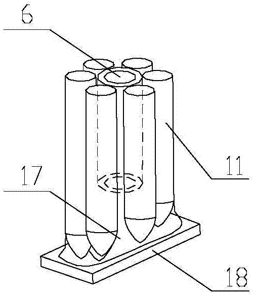
[0050] 1) The droplet adsorbs the tiny parts 18, and injects liquid into the capillary microtube 6 through the syringe to form a droplet 17 on the tip of the tungsten wire rod. The amount of the injected droplet is about 10 μl. When contacting the tiny component 18, the tiny component 18 is absorbed in the tungsten wire rod 11 lower end and is in a horizontal state. At this moment, a liquid bridge system is formed between the tiny component 18, the liquid drop and the tungsten wire rod (see figure 2 ), this step injects a certain amount of liquid into the capillary microtube through the injection device, forms tiny liquid droplets at the bottom of the tungsten wire rod, and controls the movement of the tungsten wire rod to approach the small parts to absorb the small parts;
[0051] 2) Adjust the pos...
Embodiment 3
[0057] A method for attitude control of a droplet micro-manipulator structure, comprising steps:
[0058]1) The droplet adsorbs the tiny parts 18, and injects liquid into the capillary microtube 6 through the syringe to form a droplet 17 on the tip of the tungsten wire rod. The amount of the injected droplet is about 10 μl. When contacting the tiny component 18, the tiny component 18 is absorbed in the tungsten wire rod 11 lower end and is in a horizontal state. At this moment, a liquid bridge system is formed between the tiny component 18, the liquid drop and the tungsten wire rod (see figure 2 ), this step injects a certain amount of liquid into the capillary microtube through the injection device, forms tiny liquid droplets at the bottom of the tungsten wire rod, and controls the movement of the tungsten wire rod to approach the small parts to absorb the small parts;
[0059] 2) Adjust the posture of the micro-component 18 according to the preset target posture, and the co...
PUM
 Abstract
Description
Claims
Application Information
 - R&D
- Intellectual Property
- Life Sciences
- Materials
- Tech Scout
- Unparalleled Data Quality
- Higher Quality Content
- 60% Fewer Hallucinations
Browse by: Latest US Patents, China's latest patents, Technical Efficacy Thesaurus, Application Domain, Technology Topic, Popular Technical Reports.
© 2025 PatSnap. All rights reserved.Legal|Privacy policy|Modern Slavery Act Transparency Statement|Sitemap|About US| Contact US: help@patsnap.com


