
Base device for hydraulic fracturing experiment

A hydraulic fracturing and experimental technology, applied in the field of hydraulic fracturing, can solve the problems of difficulty in ensuring the integrity of rock samples, inability to ensure the in-situ morphology of cracks, and difficulty in ensuring the integrity of samples, and achieves light weight and simple structure. , the effect of small overall size

Pending Publication Date: 2020-06-02
RES INST OF SHAANXI YANCHANG PETROLEUM GRP +1
View PDF0 Cites 0 Cited by
  • Summary
  • Abstract
  • Description
  • Claims
  • Application Information

AI Technical Summary

Problems solved by technology

[0003] The above experimental method has the following problems: After the fracturing experiment is completed, the rock sample needs to be disassembled. During the disassembly process, because the bond between the sample and the steel pipe is usually a high-strength adhesive, it is difficult to disassemble the sample. , even if the sample can be disassembled, it is difficult to ensure the integrity of the sample, and the in-situ shape of the crack cannot be guaranteed
After the integrity of the sample is destroyed, if the CT scan is performed again, the experimental results will be inaccurate, which will lead to a decrease in the reliability of the experimental results.
[0004] At present, most fracturing experiments use the above method, which has a series of problems such as difficult operation, difficulty in ensuring the integrity of rock samples, and ensuring the in-situ shape of fractures.

Method used


Image

  • Base device for hydraulic fracturing experiment
  • Base device for hydraulic fracturing experiment
  • Base device for hydraulic fracturing experiment

Examples


Embodiment Construction

[0027] The specific implementation of the base device will be further described below in conjunction with the accompanying drawings:

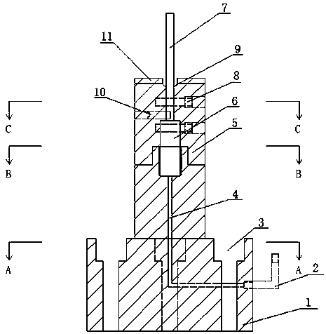
[0028] As shown in Figure 1, the base device proposed by the present invention for fracturing experiments is mainly composed of a base body 1, a transfer elbow 2, a dismantling column 5, a fracturing joint 6, a fracturing steel pipe 7, and a thin metal ring 11 and so on.

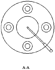
[0029] There are connecting holes on the main body 1 of the base, and are connected with the experimental apparatus through four base connecting bolts 3 . There is a flow channel 4 for fracturing fluid in the base body 1, and an adapter elbow 2 is connected to the side of the base body 1 to connect with the flow channel for the circulation of fracturing fluid.

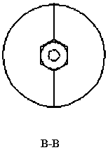
[0030] The lower end of the dismantling post 5 is connected to the outer thread on the base body 1 through its internal internal thread, and the upper end is provided with a thin metal ring 11 as a spacer.

[0031] ...


PUM

PropertyMeasurementUnit
diameteraaaaaaaaaa
diameteraaaaaaaaaa

Abstract

The invention provides a base for a hydraulic fracturing experiment. The base comprises a base main body, an adapter bend, a dismounting column, a fracturing connector and a fracturing steel pipe. Thebase main body provides a flowing channel for a fracturing fluid and other parts of a fixing device, the adapter bend is used for connecting the high-pressure liquid and the base main body, the dismounting column is formed by connecting a left half part and a right half part through a bolt, and a hollow cavity allowing the fracturing steel pipe to penetrate through is defined in the center of thedismounting column. The fracturing steel pipe penetrates through the dismounting column, the upper end of the fracturing steel pipe extends out to be connected with a sample, and the fracturing connector is arranged at the lower portion of the fracturing steel pipe and is connected with the base main body to communicate the flowing channel with the fracturing steel pipe. According to the device,the base main body and the dismounting column are combined, the dismounting column fixes the sample in the fracturing process, after fracturing, the left half part and the right half part are separated, then the fracturing steel pipe is exposed, and the fracturing steel pipe and the base main body can be separated through a hand vise. The design is ingenious and reasonable, the rock sample can beeasily disassembled, the nondestructive operation can be achieved, the integrity of the sample is better kept, and the in-situ form of cracks is guaranteed.

Description

technical field [0001] The invention belongs to the technical field of hydraulic fracturing, and in particular relates to equipment and device technology in hydraulic fracturing experiments. Background technique [0002] When doing indoor hydraulic fracturing experiments, the general method used is to drill a circular hole of a certain size in the center of a cylindrical or cubic rock specimen to prefabricate a wellbore, and use a fracturing steel pipe to simulate a vertical wellbore. At the same time, an open-hole section of a certain size needs to be reserved, which can simulate the initial fractures appearing in this well section during the fracturing process. A high-strength steel pipe is inserted into the round hole, and the gap between the steel pipe and the prefabricated wellbore is sealed with a high-strength adhesive. After fracturing, it is necessary to remove the rock specimen for further CT tomographic scanning to obtain the influence of the fracturing fracture ...

Claims


Application Information

Patent Timeline
Patent Type & Authority Applications(China)
IPC IPC(8): G01N3/12G01N3/02E21B43/26
CPCE21B43/26G01N3/02G01N3/12G01N2203/0019G01N2203/0048G01N2203/0067G01N2203/0641
Inventor 张成朋穆景福卢义玉孙晓汤积仁郭兴周军平罗攀丁选明程鹏龙坤
Owner RES INST OF SHAANXI YANCHANG PETROLEUM GRP
Learn More