
Hub temperature detecting and cooling control system

A technology for cooling control and wheel hubs, which is applied in the direction of cooling brakes, brake safety systems, brakes, etc., can solve problems such as hub stress cracks, brake failure, safety hazards, etc., and achieve the effect of avoiding sharp and large cooling and protecting the hubs

Inactive Publication Date: 2015-11-25
ZHEJIANG DAOWEIER TECH
View PDF5 Cites 5 Cited by
  • Summary
  • Abstract
  • Description
  • Claims
  • Application Information

AI Technical Summary

Problems solved by technology

Usually, the driver manually sprays water on the brake hub to cool down the temperature based on experience. However, this method has great limitations. Some brake pads are locked due to severe wear and the driver does not notice it, resulting in high temperature and causing fires and major accidents.
In order to solve this problem, some indirect contact temperature measurement devices have been developed on the market (the brake hub of the car is rotating, which is not convenient for direct temperature measurement). However, because these devices are indirect temperature measurement, the response speed is slow, and it is easy to Serious consequences such as brake failure and tire blowout
In addition, due to the large temperature difference between the cooling water used to spray onto the hub and the high-temperature hub, under the stimulation of rapid cooling of the cooling water for a long time, stress cracks will occur in the internal structure of the hub, which will greatly reduce the life of the hub. At the same time, serious safety hazards

Method used


Image

  • Hub temperature detecting and cooling control system

Examples


Embodiment Construction

[0019] In order to make the present invention be further understood, the present invention will be further described below with reference to accompanying drawing and specific embodiment of description:

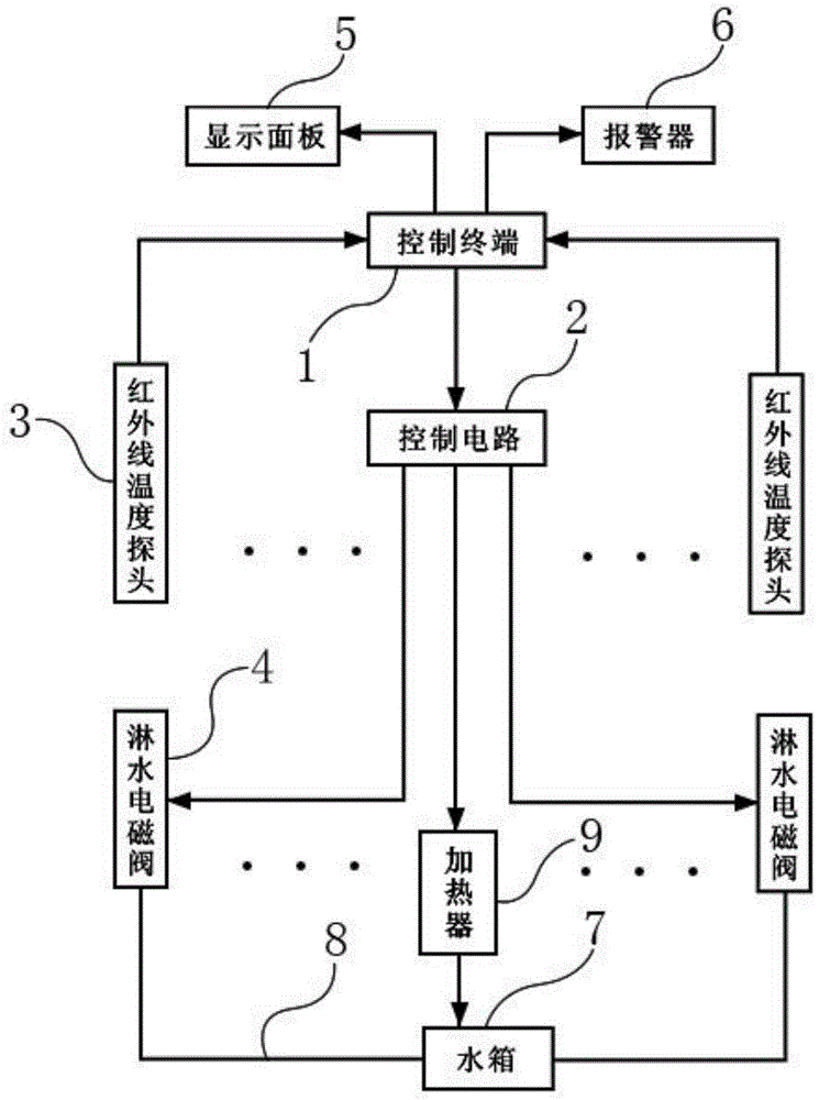
[0020] like figure 1 As shown, a wheel hub temperature detection and cooling control system includes a control terminal 1, a water tank 7, a water spray solenoid valve 4, and a temperature probe arranged at the wheel hub. The signal output end of the temperature probe is connected to the signal input end of the control terminal 1 , and the signal output end of the control terminal 1 is connected to the signal input end of the water spray solenoid valve 4 . Corresponding water delivery pipes 8 are provided between the water tank 7 and each wheel hub, and the water delivery pipes 8 are controlled on and off by the water spray solenoid valve 4 . Wherein, as an improvement of the present invention, the temperature probe is a non-contact temperature probe, specifically an infrared...


PUM


Abstract

The invention discloses a hub temperature detecting and cooling control system, and relates to the field of temperature control of automobiles. The problems that in the prior art, the temperature measurement response is slow and the error is large are solved. The system comprises a control terminal, a water tank, water spraying electromagnetic valves and infrared temperature probes arranged on hubs. Corresponding water conveying pipes are arranged between the water tank and all the hubs. The water spraying electromagnetic valves used for controlling the water conveying pipes to be opened and closed are arranged in the water conveying pipes respectively. A heater is arranged in the water tank. The heater and the water spraying electromagnetic valves are all connected with the control terminal. The infrared temperature probes are used for collecting temperatures of the hubs and uploading the temperatures to the control terminal where the upper temperature limit value is set. When the temperatures of the hubs are detected to be too high, the control terminal controls the water spraying electromagnetic valves to be opened, and water in the water tank is sprayed onto the hubs through the water conveying pipes to cool the hubs. When the temperatures of the hubs are lowered to a certain value, the water spraying electromagnetic valves are closed. The hub temperature detecting and cooling control system is high in accuracy, low in power consumption and good in stability, the temperatures of the hubs can be collected to the control terminal to be displayed in real time, and the hubs can be cooled in a dynamic equilibrium manner.

Description

technical field [0001] The invention relates to the field of automobile temperature control, in particular to a wheel hub temperature detecting and cooling control system that monitors the temperature of a brake hub in real time based on infrared temperature measurement technology, sends an alarm when the temperature exceeds a set temperature, and automatically realizes the cooling control of the brake hub. Background technique [0002] As an important transmission support part of a car, the health of the wheel hub is particularly important to the driving safety of the car. When the hub is braked, there will be a sharp and rapid heat accumulation between the hub and the brake pad, forming a hot zone on the end face of the hub. At present, when large-scale freight and passenger vehicles brake suddenly during driving or brake on uphill and downhill roads, the brake pads and brake hubs will be locked for a short time to generate high temperatures. Usually the driver manually s...

Claims


Application Information

Patent Timeline
Patent Type & Authority Applications(China)
IPC IPC(8): B60T5/00B60T17/22
Inventor 王晓东张朋辉张锋
Owner ZHEJIANG DAOWEIER TECH
Learn More