
Heat Treatment Tube Furnace

A tube furnace and furnace tube technology, which is applied in the field of heat treatment, can solve the problems that heat treatment cannot be carried out in a set environment, and the object to be treated is in contact with air.

Active Publication Date: 2017-07-07
HARBIN INST OF TECH AT WEIHAI
View PDF4 Cites 0 Cited by
  • Summary
  • Abstract
  • Description
  • Claims
  • Application Information

AI Technical Summary

Problems solved by technology

[0007] The purpose of the present invention is to provide a heat treatment tube furnace to solve the problem that the heat treatment cannot be carried out in the set environment due to the stir frying of the operator during the heat treatment process, which causes the object to be treated to be in contact with the air

Method used


Image

  • Heat Treatment Tube Furnace
  • Heat Treatment Tube Furnace
  • Heat Treatment Tube Furnace

Examples


Embodiment Construction

[0045] The embodiment of the present invention provides a tube furnace for heat treatment, which solves the problem that the heat treatment cannot be carried out in the set environment due to the stir-frying of the operator during the heat treatment process, which causes the object to be treated to be in contact with the air.

[0046] In order to enable those skilled in the art to better understand the technical solutions in the embodiments of the present invention, and to make the above-mentioned purposes, features and advantages of the embodiments of the present invention more obvious and understandable, the technical solutions in the embodiments of the present invention are described below in conjunction with the accompanying drawings The program is described in further detail.

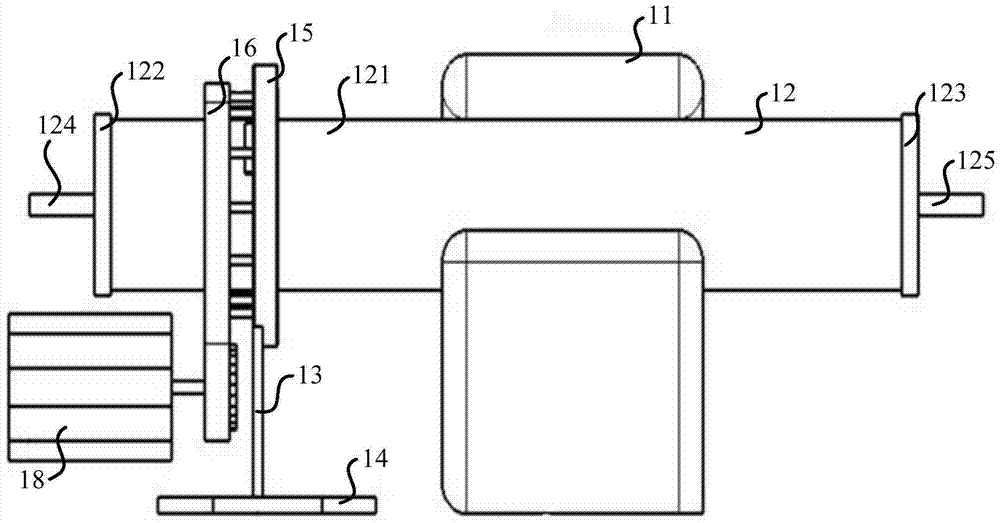
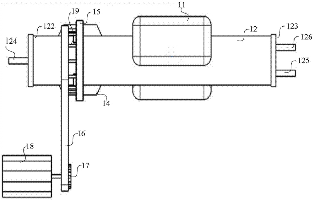
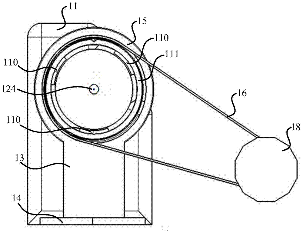
[0047] Please refer to the attached Figure 1-4 , an embodiment of the present invention provides a tube furnace for heat treatment. The provided tube furnace for heat treatment includes a heating...


PUM


Abstract

The heat treatment tubular furnace provided by the present invention includes a heating element, a furnace tube, a first support, a driving device, a loading container, a second support, a bearing, a first group of magnets and a second group of magnets; the furnace tube is connected to the heating element; The first support is fixed on the installation foundation and is fixedly connected with the outer ring of the bearing; the inner ring of the bearing is sleeved on the furnace tube, and there is a gap between the outer wall of the furnace tube; the first group of magnets is distributed in the circumferential direction of the inner ring; the driving device and The inner ring is connected to drive the inner ring to rotate around the furnace tube; the loading container is set in the furnace tube through the second support, and the inner cavity of the loading container communicates with the inner cavity of the furnace tube; the part where the second support is connected to the inner wall of the furnace tube is provided with rollers The second group of magnets is connected with the second support and distributed along the circumferential direction of the inner wall of the furnace tube; the second group of magnets is relatively distributed with the first group of magnets, and has different polarities. The above solution can solve the problem that the heat treatment cannot be carried out in the set environment due to the stir frying by the operator, which causes the object to be treated to be in contact with the air.

Description

technical field [0001] The invention relates to the technical field of heat treatment, and more specifically, relates to a tube furnace for heat treatment. Background technique [0002] In the field of mechanical processing, some materials or workpieces usually need to undergo heat treatment to change their properties in certain aspects. In the process of heat treatment, the operator needs to first heat the material or workpiece to a suitable temperature in a medium such as atmosphere or oil, then keep it at this temperature for a set time, and finally cool it at a certain cooling rate. It can be seen that heating, heat preservation and cooling are three essential processes of heat treatment, among which, the uniformity of heating is an important guarantee of heat treatment quality. [0003] In the field of powder metallurgy, the early modification or pretreatment of the powder through heat treatment will have a huge impact on the performance of the workpiece produced later...

Claims


Application Information

Patent Timeline
Patent Type & Authority Patents(China)
IPC IPC(8): C21D9/00C21D1/74
Inventor 崔国荣张文丛杨博
Owner HARBIN INST OF TECH AT WEIHAI
Learn More