Crucible structure

A crucible and crucible bottom technology, applied in the field of crucible structure, can solve the problem of uneven thickness of evaporation layer

Active Publication Date: 2015-11-25
BOE TECH GRP CO LTD
View PDF9 Cites 11 Cited by
  • Summary
  • Abstract
  • Description
  • Claims
  • Application Information

AI Technical Summary

Problems solved by technology

[0003] The invention provides a crucible structure, which is used to solve the problem of uneven thickness of the evaporation layer formed on the substrate when point source evaporation is used

Method used


Image

  • Crucible structure
  • Crucible structure
  • Crucible structure

Examples


Embodiment Construction

[0035] In order to make the purpose, technical solutions and advantages of the embodiments of the present invention more clear, the following will clearly and completely describe the technical solutions of the embodiments of the present invention in conjunction with the drawings of the embodiments of the present invention. Apparently, the described embodiments are some, not all, embodiments of the present invention. Based on the described embodiments of the present invention, all other embodiments obtained by persons of ordinary skill in the art without creative efforts shall fall within the protection scope of the present invention.

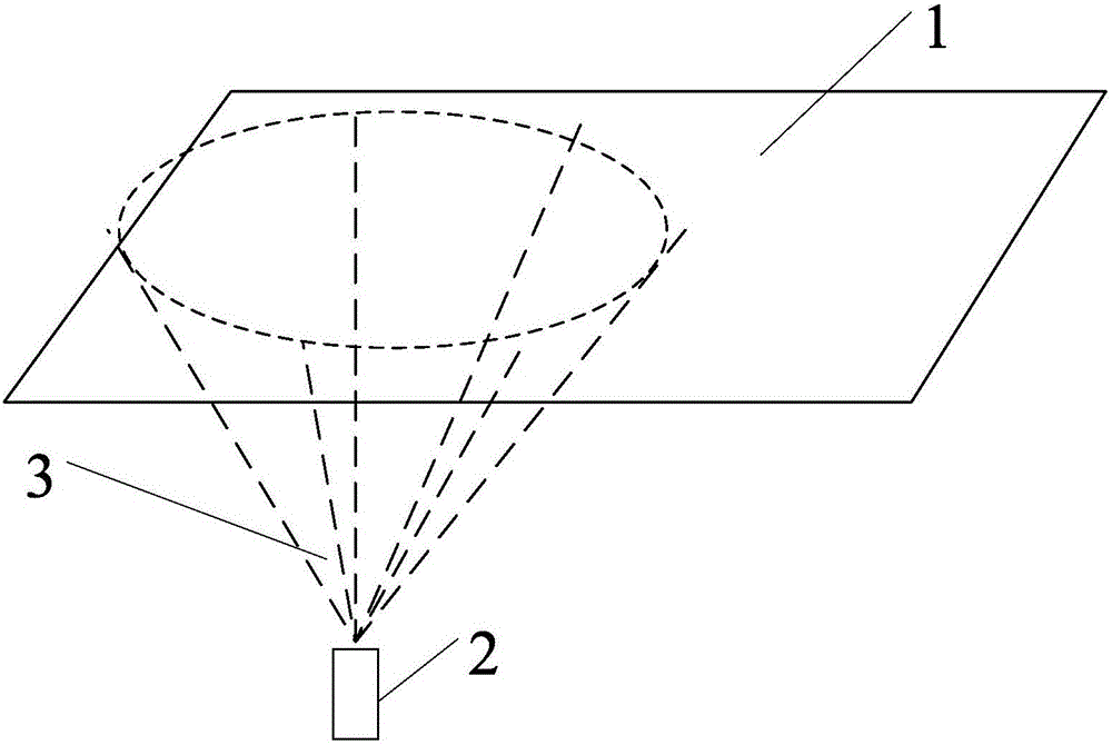
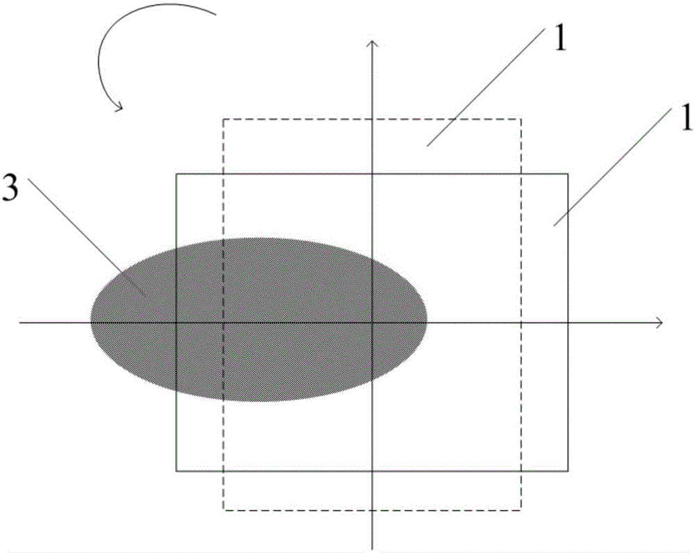
[0036] Currently used point source evaporation processes such as figure 1 shown. figure 1 In the method, the material source is placed in the crucible 2, and after the material source is heated, the evaporation gas flow generated by the material source evaporates from the upper opening of the crucible. At the outlet of the crucible, the densit...


PUM

PropertyMeasurementUnit
angleaaaaaaaaaa
angleaaaaaaaaaa

Abstract

The invention relates to a crucible structure. The crucible structure comprises a crucible body and a crucible cover; the crucible body comprises a bottom wall and a crucible lateral wall, one end of the crucible lateral wall is connected with the crucible bottom wall, and the crucible cover is arranged at the other end of the crucible lateral wall; and an acute angle is formed between the crucible cover and the axis direction of the crucible, and an opening structure is arranged on the crucible cover. By means of the crucible, the evaporation area can be effectively enlarged, and the evaporation uniformity is improved.

Description

technical field [0001] Embodiments of the invention relate to a crucible structure. Background technique [0002] As the use of organic light emitting diode (OLED) display devices becomes more and more extensive, its manufacturing process is becoming more and more mature. At present, the manufacturing methods of each layer in OLED devices mainly include evaporation, spin coating and inkjet printing. Among these production methods, the evaporation method is a relatively mature method and has been used in mass production. The low-generation line generally uses the evaporation mode, and mostly uses the point source evaporation method. When using a point source as the evaporation method, since the point source only exists in a certain position in the cavity, in order to ensure the uniformity of the evaporation of the substrate, it is generally necessary to rotate the substrate. However, this method of ensuring the uniformity of the evaporation by rotating the substrate often ...

Claims


Application Information

Patent Timeline
Patent Type & Authority Applications(China)
IPC IPC(8): C23C14/24
CPCC23C14/243
Inventor 赵德江王浩
Owner BOE TECH GRP CO LTD
Why Eureka
Try Eureka