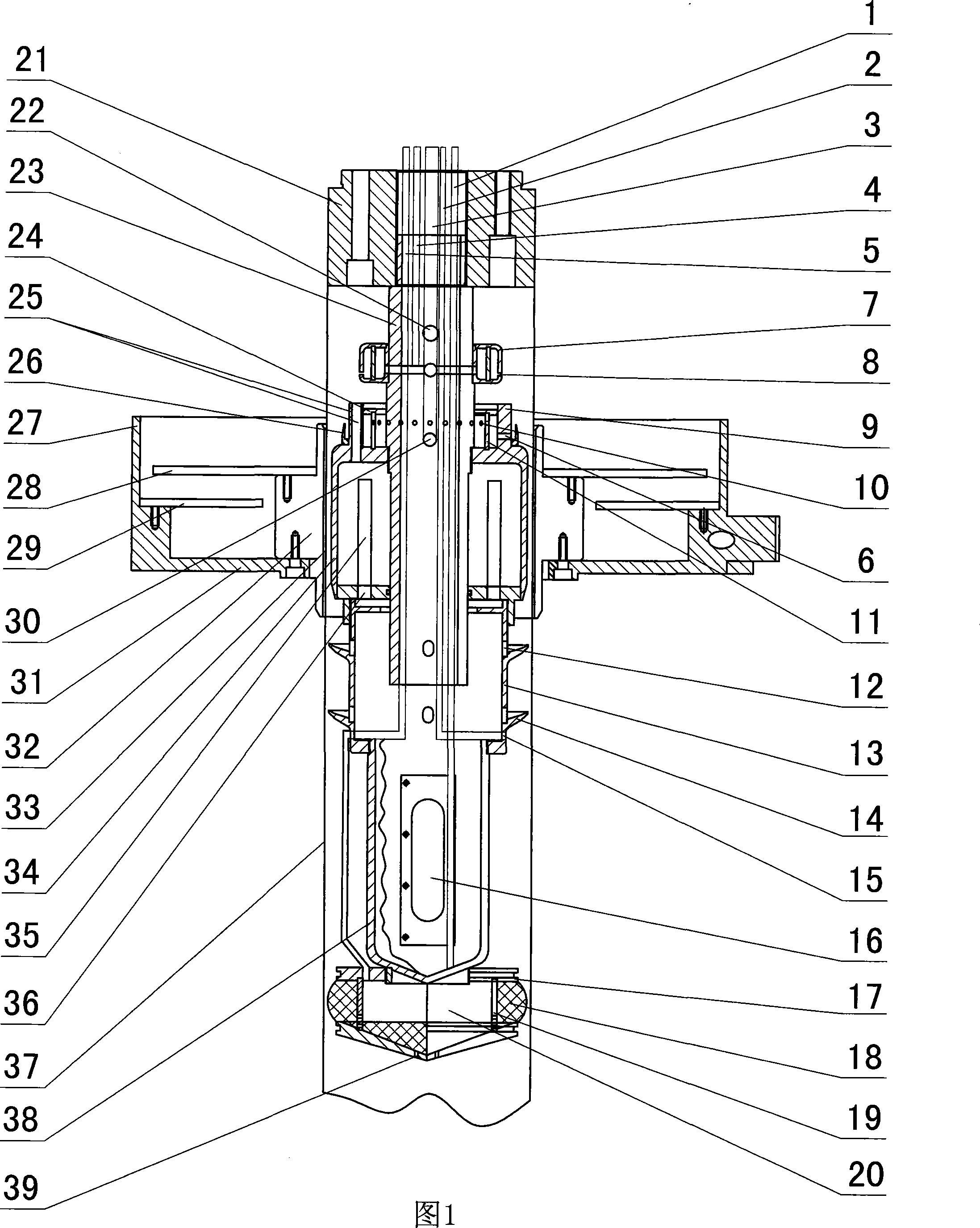
Film cooling forming device of film-blowing machine

A film cooling and forming device technology, which is applied in the field of film cooling and forming devices of film blowing machines, can solve the problems of uneven thickness of film blank tubes, difficult design, high manufacturing cost, etc., achieve fast and uniform cooling speed, and highlight the essence Features, the effect of low manufacturing cost

Inactive Publication Date: 2008-05-14
李志淮
View PDF0 Cites 4 Cited by
  • Summary
  • Abstract
  • Description
  • Claims
  • Application Information

AI Technical Summary

Problems solved by technology

[0002] At present, the production of BOPP (tube film biaxially oriented polypropylene film) type film machines is mainly based on the flat film method, but the flat film method has a complex structure and high cost, which brings economic difficulties to the manufacturer to purchase the machine; Another type of film blowing machine with tube film method uses indirect cooling of the cooling tank and the method of photoelectric bubble stabilization outside the tube blank. The design is very difficult, the manufacturing cost is also high, and the cooling effect is not ideal, and the PP material comes out After the die opening, it will crystallize rapidly, so that the next step of stretching cannot be carried out. In addition, this kind of machine uses air-conditioning to shape, cool and control the thickness of the film blank tube, so there is still an error in the thickness of the film blank tube, making the film blank The thickness of the tube is uneven. According to the deficiencies of the existing technology, the film cooling forming device of the BOPP film machine needs to be improved to meet the needs of the manufacturer.

Method used


Image

  • Film cooling forming device of film-blowing machine

Examples


Embodiment Construction

[0013] With reference to accompanying drawing, the film cooling forming device of this kind of film blowing machine includes air inlet tray 7, inner cooling water divider bucket 34, outer cooling water ring 27, wiper bucket 13, water receiving bucket 38 and water suction tank 17. Disk 7 is arranged on the top of inner cooling bucket 34, and said air inlet disk 7 communicates with an air inlet pipe 4, said air inlet disk 7 is provided with air outlet 8, and the top of said inner cooling water bucket 34 has exhaust hole 22, the exhaust hole 22 is arranged on an exhaust pipe 23; the upper end of the outer cooling water ring 27 is open, and it is set outside the inner cooling water dividing bucket 34, and there is a film blank tube channel 33 between the two. The outer cooling water ring 27 can move up and down, so that when the film base just starts to cool, the outer cooling water ring 27 can be moved away from the inner cooling water dividing bucket 34, so as to prevent the oute...


PUM


Abstract

The invention discloses a film cooling molding apparatus for the film blower, which comprises an intake plate, an inner cooling water diversion barrel, an outer cooling water ring, a water-scraping barrel, a water-collecting barrel and a water absorption container. The intake plate is arranged on the upper of the inner water diversion cooling barrel; the intake plate is connected with an inlet pipe; the upper end of the outer cooling water ring is open and is covered out of the inner water diversion cooling barrel; a water inlet hole is arranged at upper part of the inner water diversion cooling barrel; a water inlet pipe is arranged at the water inlet hole; the water-scraping barrel and the water-collecting barrel are arranged in sequence under the inner water diversion cooling barrel and the water-scraping barrel; the water-collecting barrel and the inner water diversion cooling barrel are communicated with each other; a pumping pipe is connected with the water-collecting barrel; the water absorption container is arranged under the water-collecting barrel; the water absorption container is provided with a water absorption sponge and the water absorption container is connected with a suction pipe. With simple structure and low production cost, the invention has the advantages that the inside and outside water is contacted with the film base directly; the fast and even cooling is achieved; the problems of poor cooling and non-uniform thickness of the film base in prior art are solved.

Description

technical field [0001] The invention relates to an improved invention of a film cooling forming device of a film blowing machine, in particular to a cooling forming device of a bidirectional synchronous stretching film blowing machine. Background technique [0002] At present, the production of BOPP (tube film biaxially oriented polypropylene film) type film machines is mainly based on the flat film method, but the flat film method has a complex structure and high cost, which brings economic difficulties to the manufacturer to purchase the machine; Another type of film blowing machine with tube film method uses indirect cooling of the cooling tank and the method of photoelectric bubble stabilization outside the tube blank. The design is very difficult, the manufacturing cost is also high, and the cooling effect is not ideal, and the PP material comes out After the die opening, it will crystallize rapidly, so that the next step of stretching cannot be carried out. In addition...

Claims


Application Information

Patent Timeline
Patent Type & Authority Applications(China)
IPC IPC(8): B29C55/28B29C35/16
Inventor 李志淮
Owner 李志淮
Why Eureka
Try Eureka