Variable-diameter back reaming device and process method

A reverse reaming and variable-diameter technology, applied in drilling equipment and methods, earthwork drilling, drilling equipment, etc., can solve the problems of large outer diameter of the stabilizer, high risk of stuck pipe, low efficiency, etc., to ensure reliable High performance, smooth movement, and safety

Active Publication Date: 2015-11-25
PETROCHINA CO LTD
View PDF5 Cites 2 Cited by
  • Summary
  • Abstract
  • Description
  • Claims
  • Application Information

AI Technical Summary

Problems solved by technology

The disadvantages of this method are as follows: the cutting ability of the inclined surface at the upper end of the stabilizer is limited, it takes a lot of time to correct the well wall, and the efficiency is low; in addition, the outer diameter of the fixed stabilizer is large, and the risk of pipe sticking is high

Method used


Image

  • Variable-diameter back reaming device and process method
  • Variable-diameter back reaming device and process method
  • Variable-diameter back reaming device and process method

Examples


Embodiment 1

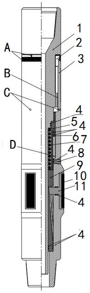
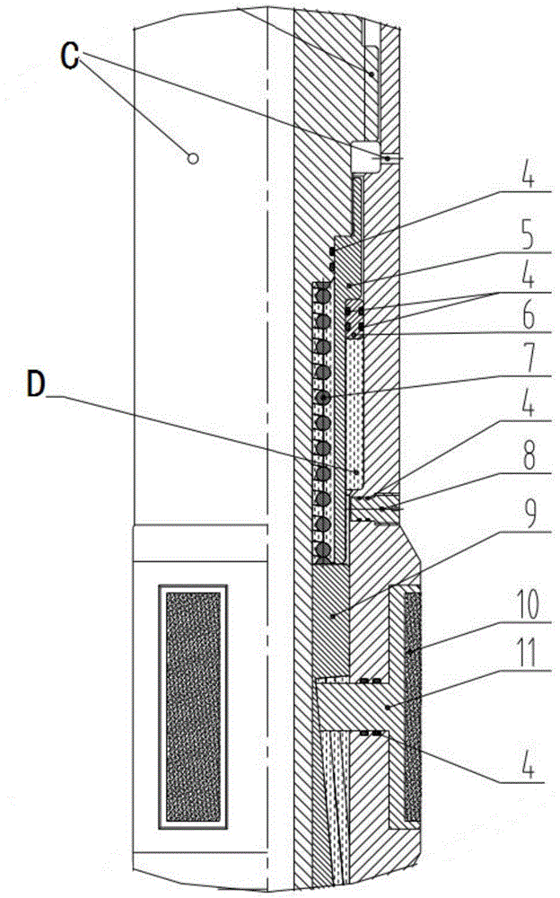
[0048] Embodiment 1: as figure 1 , figure 2 , image 3 with Figure 4 As shown, a variable diameter reamer, the central rod 1 and the body 3 are connected by a spline pair B, the body 3 has a through hole C, the upper part of the body 3 is provided with a load-bearing end cover 2, and the middle part of the body 3 is 3 Ridge or 4-rib structure, 2 oil injection holes are arranged symmetrically above the rib and an oil filling plug 8 is installed, and a cutting block 11 is arranged on each rib; the annular space between the center rod 1 and the body 3 is equipped with a balance piston rod 5 and a balance piston 6. The spring 7, the inclined cylinder 9, the balance piston rod 5 is connected with the center rod 1 through threads, the balance piston 6 is installed in the ring space between the balance piston rod 5 and the body 3, and the spring 7 is installed between the balance piston rod 5 and the center rod 1 between.

[0049] The specific implementation process of the pres...

Embodiment 2

[0063] Embodiment 2: as figure 1 , figure 2 , image 3 with Figure 4 As shown, a variable diameter reamer includes a central rod, a load-bearing end cover, a body, a balance piston rod, a balance piston, a spring, an oil plug, an inclined cylinder, and a cutting block. The center rod 1 and the body 3 Connect and form an annulus, the annulus is provided with a balance piston rod 5, a balance piston 6, a spring 7, and an inclined cylinder 9, the balance piston rod 5 is connected with the center rod 1, and the incline cylinder 9 is placed at the lower part of the balance piston rod 5. A spring 7 is arranged in the annular space formed by the piston rod 5 and the central rod 1, a balance piston 6 is set on the balance piston rod 5, and a through hole C is opened on the body 3, and the through hole C is respectively connected with the upper cavity of the balance piston rod 5 and The well wall annulus is connected.

[0064] A preferred embodiment of the present invention is th...

Embodiment 3

[0074] Embodiment 3: as figure 1 , figure 2 , image 3 with Figure 4 As shown, a variable diameter reamer includes a center rod 1, a load-bearing end cover 2, a body 3, a sealing ring 4, a balance piston rod 5, a balance piston 6, a spring 7, an oil plug 8, and a bevel cylinder 9 , Cemented carbide block 10, cutting block 11, etc. The central rod 1 and the body 3 are connected by a spline pair B, the body 3 has a through hole C, the upper part of the body 3 is provided with a load-bearing end cover 2, the middle part of the body 3 is a structure of 3 to 4 ribs, and two oil injection holes are arranged symmetrically above the ribs Hole and install oil injection plug 8, each edge is provided with cutting block 11, on the cutting block, cemented carbide block 10 is inlaid. The annulus between the center rod 1 and the body 3 is equipped with a balance piston rod 5, a balance piston 6, a spring 7, and an inclined plane cylinder 9. The balance piston rod 5 is connected to the ...


PUM


Abstract

The invention provides a variable-diameter back reaming device and a process method. According to the variable-diameter back reaming device, a central rod is connected with a body by a spline pair, through holes are formed in the body, a bearing end cover is arranged on the upper part of the body, the middle part of the body is of a three-ledge or four-ledge structure, two oil injection holes are symmetrically formed above the ledges and an oil injection plug head is installed, and a cutting block is arranged on each ledge; and a balance piston rod, a balance piston, a spring and a bevel barrel are installed in an annular space of the central rod and the body, the balance piston rod is connected with the central rod through a thread, the balance piston is installed in an annular space of the balance piston rod and the body, and the spring is installed between the balance piston rod and the central rod. The variable-diameter back reaming device and the process method provided by the invention are used for safe drilling and completion for complex formations.

Description

technical field [0001] The invention relates to a variable-diameter back reamer and a process method, belonging to the technical field of downhole tools for drilling engineering. Background technique [0002] During the drilling process, when drilling to the well section in the formation that is prone to necking, the drilling tool is likely to encounter resistance and jamming during the lifting process. At present, the back reaming operation is often used to solve this problem, that is, the upper inclined surface of the fixed drilling tool stabilizer (hard alloy is surfacing on this surface) is used to repair the well wall first, and after the stabilizer is lifted and passed, the drill bit is used for repairing. well wall. The disadvantages of this method are as follows: the cutting ability of the inclined surface at the upper end of the stabilizer is limited, it takes a lot of time to correct the well wall, and the efficiency is low; in addition, the outer diameter of the ...

Claims


Application Information

Patent Timeline
Patent Type & Authority Applications(China)
IPC IPC(8): E21B7/28
Inventor 王勇茗高云文吴学升赵巍王彦博黄占盈张燕娜周文军段志锋胡东峰余世福叶文勇徐自强刘峰
Owner PETROCHINA CO LTD
Why Eureka
Try Eureka