High-pressure hydraulic jetting device

A technology of hydraulic jetting and high pressure, applied in the fields of production fluids, wellbore/well components, earthwork drilling, etc., can solve the problems of poor jetting effect and complicated nozzle structure, and achieve the advantages of low friction, flexible rotation and increased jetting range. Effect

Inactive Publication Date: 2015-11-25
CHENGDU LAIBAO PETROLEUM EQUIP
View PDF8 Cites 0 Cited by
  • Summary
  • Abstract
  • Description
  • Claims
  • Application Information

AI Technical Summary

Problems solved by technology

[0003] In order to solve the defects of complex nozzle structure and poor spraying effect, the present invention provides a high-pressure hydraulic spraying device

Method used


Image

  • High-pressure hydraulic jetting device

Examples


Embodiment 1

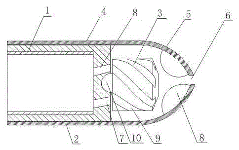
[0018] Such as figure 1 As shown, a high-pressure water jet device includes a connecting body 1, a housing 2, a rotor 3, the connecting body 1 is a cavity structure with an open rear end, and the housing 2 is composed of a hollow cylinder 4 and a hollow hemisphere 5 that are connected, The hollow cylinder 4 is sleeved on the outer wall of the connecting body 1 through a threaded connection, the hollow hemisphere 5 is provided with a water outlet 6 on the top of the sphere; the rotor 3 is rotatably arranged at the bottom of the connecting body 1, and the bottom of the connecting body 1 is evenly provided with impact spray Hole 7; also includes a pressure block 8 evenly arranged on the inner arc surface of the hollow hemisphere 5 around the water outlet 6.

[0019] In this embodiment, the high-pressure pipeline is fixed to the connecting body 1 through the opening on the rear end of the connecting body 1, and the high-pressure liquid input by the high-pressure pipeline enters the c...

Embodiment 2

[0021] In this embodiment, on the basis of embodiment 1, the pressure block 8 is made of rubber material.

[0022] The pressing block 8 is made of rubber material, which effectively improves the pressing effect.

Embodiment 3

[0024] In this embodiment, on the basis of embodiment 1 or embodiment 2, the impact nozzle hole 7 is arranged obliquely at the bottom of the connecting body 1, and the side wall of the rotor 3 is evenly provided with grooves 9 which rotate in the same direction as The impingement nozzle holes 7 are arranged obliquely in opposite directions.

[0025] The impingement nozzle hole 7 is arranged obliquely and the groove 9 is rotated in the opposite direction to that of the impingement nozzle hole 7, so that the liquid passing through the impingement nozzle hole 7 can generate a circumferential force when the surface of the rotor 3 is impacted, so that the rotor 3 Capable of high-speed rotation.


PUM


Abstract

The invention provides a high-pressure hydraulic jetting device, which comprises connecting bodies, cases and a rotating head, wherein each connecting body is of a cavity structure with an opening formed in the back end surface; each case consists of a hollow cylinder and a hollow hemisphere which are communicated and connected; each hollow cylinder is connected onto the outer wall of the corresponding connecting body through screw threads in a sleeving way; the sphere top of each hollow hemisphere is provided with a water outlet; the rotating head is rotationally arranged at the bottom of the connecting bodies; the bottom of each connecting body is uniformly provided with impact jetting holes; and the high-pressure hydraulic jetting device also comprises pressurizing blocks uniformly arranged on the inner circular arc surfaces of the hollow hemispheres around the water outlets. By arranging the pressurizing blocks, the liquid pressure is raised when rotated liquid flows through the water outlets; the high-pressure liquid is effectively atomized; and the jetting range of the high-pressure liquid is increased.

Description

Technical field [0001] The invention relates to a spraying device, in particular to a high-pressure hydraulic spraying device. Background technique [0002] At present, it has become a common technology to use high-pressure hydraulic jet to form radial holes to increase production in the petroleum field. The main purpose is to improve the porosity and permeability parameters of the target oil layer by carrying the nozzle through the high-pressure hose to improve the output of the oil well. The high-pressure hydraulic jet radial hole-forming technology originated from the hydraulic jet flushing tubing drill pipe. Later, by improving the nozzle and related auxiliary equipment, increasing the pressure jet oil production layer, it gradually developed into an efficient and economical oilfield stimulation technology. However, the existing nozzle structure used in the petroleum field is relatively complicated and the spray effect is also poor. Summary of the invention [0003] In order...

Claims


Application Information

Patent Timeline
Patent Type & Authority Applications(China)
IPC IPC(8): E21B43/114
Inventor 谭正怀
Owner CHENGDU LAIBAO PETROLEUM EQUIP
Why Eureka
Try Eureka