Novel spray head structure for improving oil well yield

A production and new type of technology, applied in wellbore/well components, production fluids, earthwork drilling, etc., can solve problems such as poor injection effect and complex nozzle structure, and achieve the effects of low friction, flexible rotation, and increased injection range.

Inactive Publication Date: 2015-10-21
CHENGDU GAOPU PETROLEUM ENG TECH
View PDF7 Cites 0 Cited by
  • Summary
  • Abstract
  • Description
  • Claims
  • Application Information

AI Technical Summary

Problems solved by technology

[0003] In order to solve the defects such as complex nozzle structure and poor injection effect, the present invention provides a new nozzle structure to improve oil well production

Method used


Image

  • Novel spray head structure for improving oil well yield

Examples


Embodiment 1

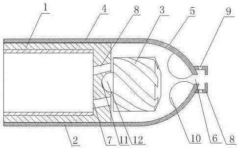
[0019] Such as figure 1 As shown, a new type of nozzle structure for improving oil well production includes a connecting body 1, a casing 2, and a rotor 3. The connecting body 1 is a cavity structure with an open rear end, and the casing 2 is connected by a hollow cylinder 4 and a hollow hemisphere. 5 components, the hollow cylinder 4 is sleeved on the outer wall of the connecting body 1 through a threaded connection, and the hollow hemisphere 5 is provided with a water outlet 6; There is an impact spray hole 7; it also includes a cover body 8 fixed on the hollow hemisphere 5, the cover body 8 is a cavity structure, and the water outlet 6 is located in the cavity structure of the cover body 8; the side wall of the cover body 8 is evenly opened Bell mouth 9 is arranged, and cover body 8 front end faces are provided with holes.

[0020] In this embodiment, the high-pressure pipeline is fixed to the connecting body 1 through the opening on the rear end surface of the connecting ...

Embodiment 2

[0022] On the basis of Embodiment 1, this embodiment also includes a pressure block 10 uniformly arranged on the inner arc surface of the hollow hemisphere 5 around the water outlet 6, and the pressure block 10 is made of rubber material.

[0023] In this embodiment, the rotated liquid will squeeze the pressurized block 10, so that the pressure of the liquid will increase, which effectively atomizes the high-pressure liquid and increases the injection range of the high-pressure liquid.

Embodiment 3

[0025] In this embodiment, on the basis of Embodiment 1 or Embodiment 2, the impact nozzle 7 is obliquely arranged at the bottom of the connecting body 1, and grooves 11 are evenly opened on the side wall of the rotor 3, and the direction of rotation of the groove 11 is consistent with that of the connecting body 1. The directions in which the impact nozzle holes 7 are inclined are opposite.

[0026] In this embodiment, the impact nozzles 7 are arranged obliquely and the direction of rotation of the groove 11 is opposite to the direction in which the impact nozzles 7 are obliquely arranged, so that the liquid passing through the impact nozzles 7 can impact the surface of the rotor 3 to produce a circumferential direction. Active force enables the rotor 3 to rotate at a high speed.


PUM


Abstract

The invention provides a novel spray head structure for improving the oil well yield. The novel spray head structure comprises a connecting body, a case and a rotating head, wherein the connecting body is of a cavity structure provided with an opening at the back end surface; the case consists of a hollow cylinder and a hollow hemisphere which are communicated and connected; the hollow cylinder is arranged on the outer wall of the connecting body in a sleeving way through screw thread connection; the top of the hollow hemisphere is provided with a water outlet; the rotating head is rotationally arranged at the bottom of the connecting body; the bottom of the connecting body is uniformly provided with impact spray holes; the novel spray head structure also comprises a cover body fixed on the hollow hemisphere; the cover body is of a cavity structure; the water outlet is positioned in the cavity structure of the cover body; and horn mouths are uniformly arranged on the side wall of the cover body. The air flow on the periphery can be sucked into the novel spray head structure through the horn mouths uniformly arranged on the side wall of the cover body; high-pressure liquid and air do composite movement and collision in the cover body; and high-pressure liquid can be atomized.

Description

technical field [0001] The invention relates to a novel nozzle structure for increasing oil well output. Background technique [0002] At present, it has become a common technology to use high-pressure water jet radial drilling to increase production in the petroleum field. It is mainly to improve the porosity and permeability parameters of the target oil layer through hydraulic injection through the high-pressure hose to carry the nozzle, so as to increase the production of the oil well. High-pressure hydraulic jet radial hole forming technology originated from hydraulic jet flushing tubing drill pipes, and later developed into an efficient and economical oilfield stimulation technology by improving nozzles and related auxiliary equipment and increasing pressure jet oil production layers. However, the structure of the existing nozzles used in the oil field is relatively complicated and the injection effect is relatively poor. Contents of the invention [0003] In ...

Claims


Application Information

Patent Timeline
Patent Type & Authority Applications(China)
IPC IPC(8): E21B43/114
Inventor 周斌
Owner CHENGDU GAOPU PETROLEUM ENG TECH
Why Eureka
Try Eureka