Shock Absorbing Structure and Balance Wheel Structure of Diaphragm Booster Pump
What is AI technical title?
AI technical title is built by Patsnap AI team. It summarizes the technical point description of the patent document.
A diaphragm pressurization and structure technology, which is applied to the components, pumps, and pump elements of the pumping device for elastic fluids, can solve the problems of mutual loosening, limited shock absorption, water leakage, etc. corner effect
Active Publication Date: 2019-02-19
FOSHAN CITY SANJIAOZHOU ELECTRICAL TECH CO LTD
View PDF16 Cites 0 Cited by
Summary
Abstract
Description
Claims
Application Information
AI Technical Summary
This helps you quickly interpret patents by identifying the three key elements:
Problems solved by technology
Method used
Benefits of technology
Problems solved by technology
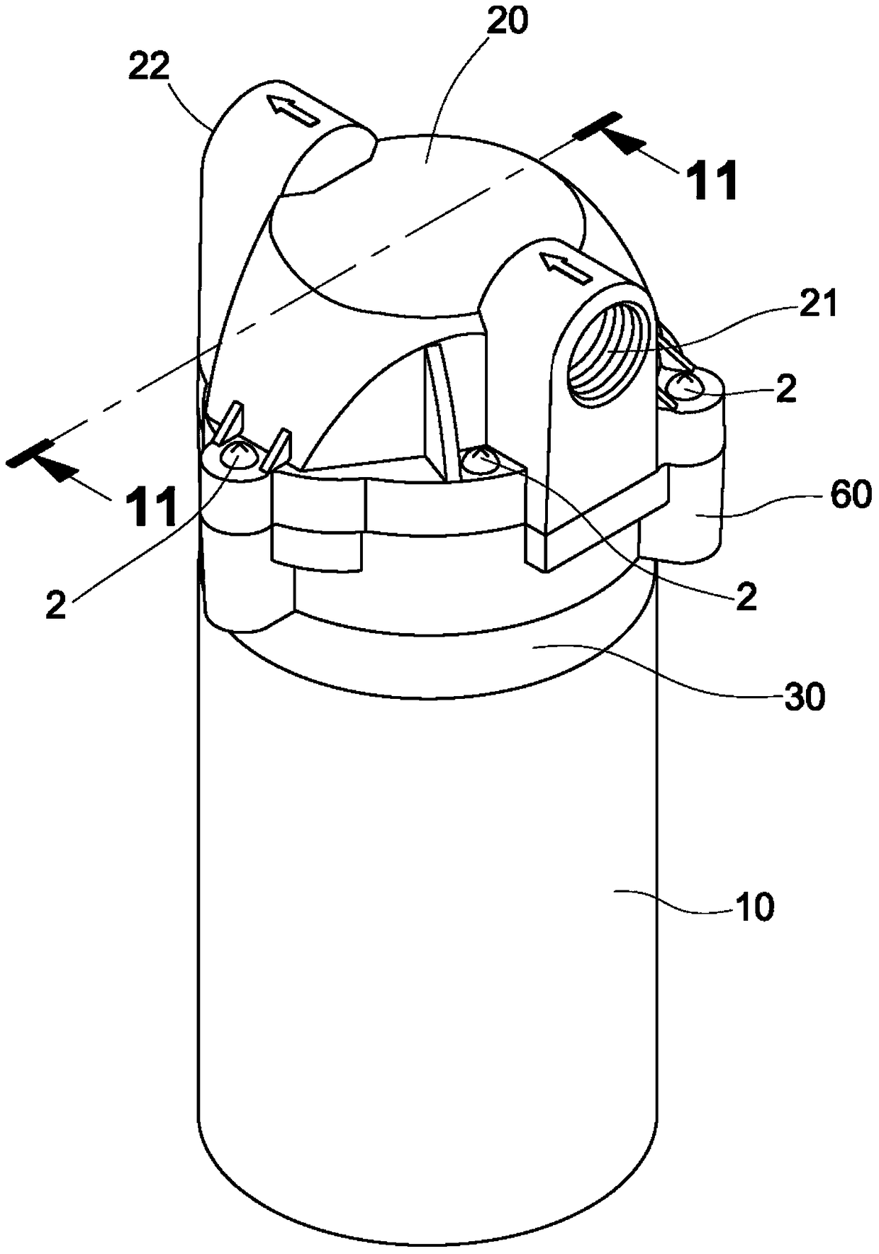
[0005] Therefore, conventional diaphragm booster pumps are all equipped with a base 100 (such as Figure 16 As shown), a pair of rubber damping pads 102 are respectively set on the two side wings 101 of the base 100, and then the base 100 is fixed on the shell C of the reverse osmosis water filter with fixing screws 103 and nuts 104; however, in practice Using the two pairs of rubber damping pads 102 on the wings 101 on both sides of the base 100 to achieve shock absorption is quite limited, because the "vibration" generated by the action of the pump body is extremely strong, and it will still cause the shell C to resonate and emit An annoying sound. In addition, the water pipe P connected to the pump head cover 20 water outlet 22 will also shake synchronously with the frequency of "vibration" (such as Figure 16 (shown by the imaginary line P in ) and slaps other components in the adjacent reverse osmosis water purifier. If it is used for a period of time, the water pipe P and its pipe joint will gradually become loose due to shaking, and finally It will lead to water leakage. Many of the aforementioned defects are caused by the "vibration" generated by the operation of the diaphragm booster pump. Therefore, how to greatly reduce the "vibration" defect caused by the operation of the diaphragm booster pump has indeed become quite urgent. Issues to be solved
Method used
Image
Click on the blue label to locate the original text in one second.
Reading with bidirectional positioning of images and text.
Examples
Embodiment Construction
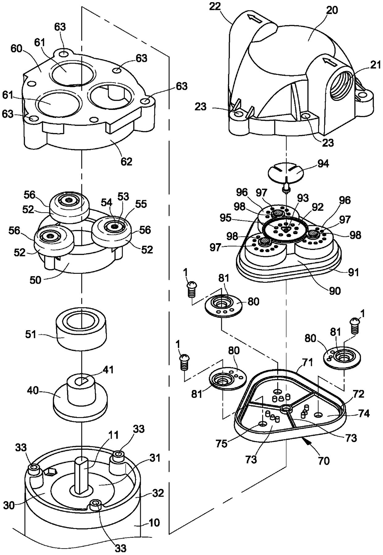
[0175] Such as Figure 19 to Figure 28 As shown, it is the first embodiment of the shock absorbing structure and the balance wheel structure of the diaphragm booster pump of the present invention, and an arc is recessed downward around the periphery of each actuating perforation 61 on the top surface of the pump head seat 60 shaped groove 64 (such as Figure 20 to Figure 22 shown), and on the bottom surface of the diaphragm 70 corresponding to the position of each arc-shaped groove 64, an arc-shaped protrusion 77 is protruded downward (such as Figure 24 and Figure 25 shown), so that after the bottom surface of the diaphragm 70 and the top surface of the pump head seat 60 are attached to each other, the three arc-shaped protrusions 77 on the bottom surface of the diaphragm 70 are completely embedded in the three arc-shaped recesses on the top surface of the pump head seat 60. In the slot 64, a shorter moment arm length L2 (such as Figure 28 shown in the enlarged view), in...
PUM
Abstract
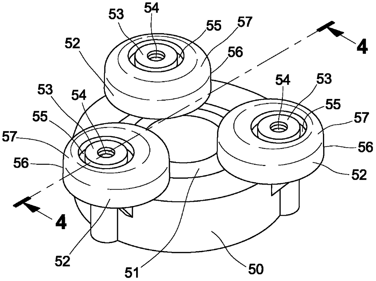
The invention relates to an improved shock absorbing structure and a balance wheel structure of a diaphragm booster pump. An arc-shaped groove is recessed downward around the periphery of each actuation perforation on the top surface of the pump head seat in the diaphragm booster pump. , and on the bottom surface of the diaphragm corresponding to the position of each arc-shaped groove, an arc-shaped protrusion is protruded downward, so that a short arm length is formed between the arc-shaped protrusion on the bottom surface of the diaphragm and the positioning protrusion ring , and the torque generated by the pump body becomes smaller when the pump body is in motion, thereby greatly reducing the intensity of "vibration". In addition, the concave ring groove is positioned on the horizontal top surface of each cylindrical balance wheel of the balance wheel seat to the vertical side surface The area of the diaphragm is set as a downward slope, so that when the diaphragm booster pump operates, there will be no "squeeze" on the bottom surface of the diaphragm.
Description
technical field [0001] The present invention is related to a diaphragm booster pump installed in a reverse osmosis purification, in particular to a structure that can greatly reduce the vibration intensity of the pump body when it is actuated, so that it can be installed in a reverse osmosis water filter After the casing is installed, it will not resonate the casing and cause annoying noises, and the cylindrical balance wheel structure of the balance wheel seat is improved, so that the pump body will not squeeze the bottom surface of the diaphragm when it is in motion " is missing. Background technique [0002] Currently known membrane booster pumps used in reverse osmosis water filters have been disclosed such as U.S. Patent Nos. 4,396,357, 4,610,605, 5,476,367, 5,571,000, 5,615,597, 5,649,812, 5,706,715, 5,791,882, and 5,816,133. Figure 1 to Figure 11 Shown, be by a motor 10, a motor front cover 30, an inclined eccentric cam 40, a balance wheel seat 50, a pump head seat 6...
Claims
Application Information
Patent Timeline
Application Date:The date an application was filed.
Publication Date:The date a patent or application was officially published.
First Publication Date:The earliest publication date of a patent with the same application number.
Issue Date:Publication date of the patent grant document.
PCT Entry Date:The Entry date of PCT National Phase.
Estimated Expiry Date:The statutory expiry date of a patent right according to the Patent Law, and it is the longest term of protection that the patent right can achieve without the termination of the patent right due to other reasons(Term extension factor has been taken into account ).
Invalid Date:Actual expiry date is based on effective date or publication date of legal transaction data of invalid patent.
Patent Type & AuthorityPatents(China)
IPC IPC(8): F04B43/04F04B53/00
CPCF04B43/0054F04B43/021F04B43/14F04B43/02
Inventor蔡应麟徐兆火
OwnerFOSHAN CITY SANJIAOZHOU ELECTRICAL TECH CO LTD

