
Overflow-free internally piloted valve

A self-control valve and liquid overflow technology, which is applied to the valve details, valve device, valve shell structure, etc., can solve the problems of shortened service life, failure to close once closed, fragility, etc., and achieve accurate and reliable performance, installation safety protection, and use convenient effect

Inactive Publication Date: 2015-11-25
朱科锋
View PDF0 Cites 1 Cited by
  • Summary
  • Abstract
  • Description
  • Claims
  • Application Information

AI Technical Summary

Problems solved by technology

There is an electronic automatic control valve, which can use sensors to display the temperature and liquid level of the water in the solar heater, and control the water at the set liquid level, but its mechanism is complex, expensive, fragile, and must be controlled by electricity; there is a mechanical Type self-control valve, the strip-shaped floating pipe extends into the water tank through the vent hole on the side of the anode heater, and the self-control valve body is plugged in the vent hole, which can leave space for the water tank when it is filled with water, but if there is no Vent hole or only one vent hole, small vent hole diameter cannot be installed, and it is a spring valve, it cannot be closed once closed, it needs many times of opening and closing to close the valve, which shortens the service life of the valve. And make the connecting pipe easy to get out of joint

Method used


Image

  • Overflow-free internally piloted valve
  • Overflow-free internally piloted valve
  • Overflow-free internally piloted valve

Examples


Embodiment Construction

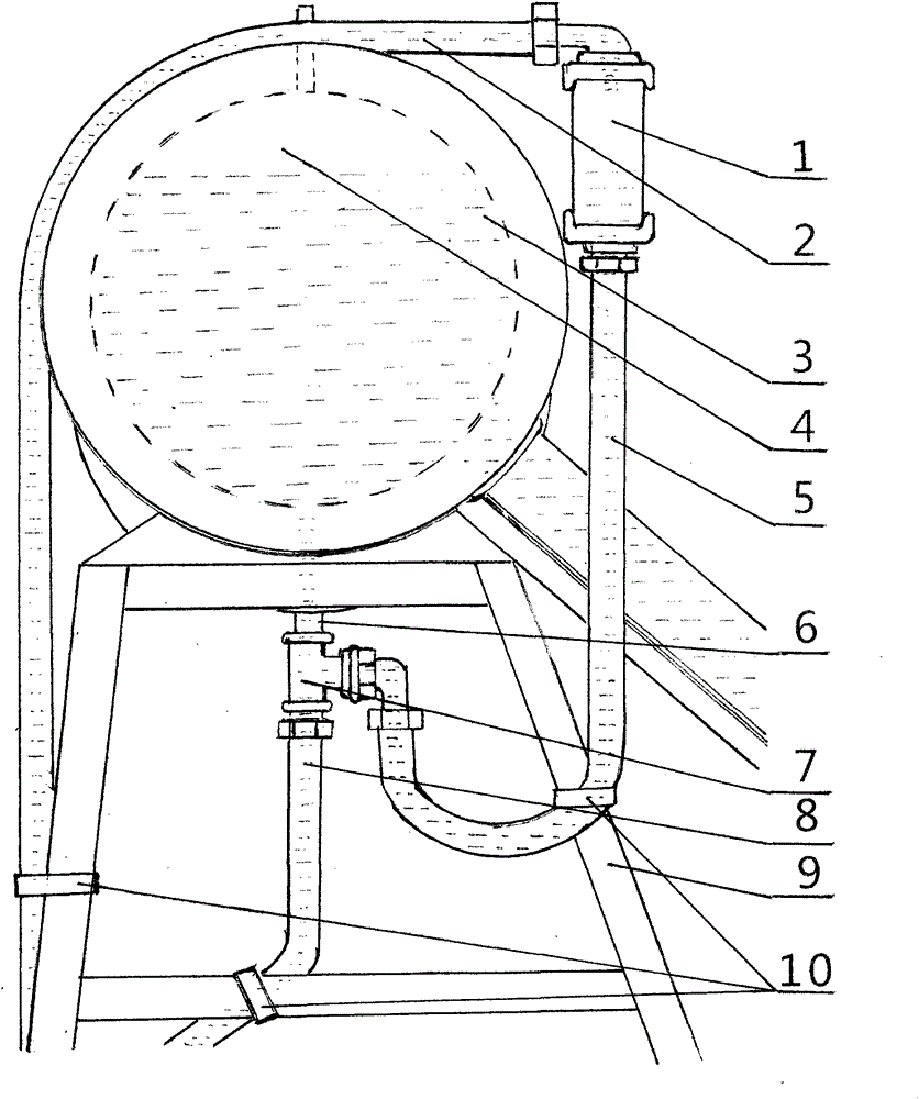
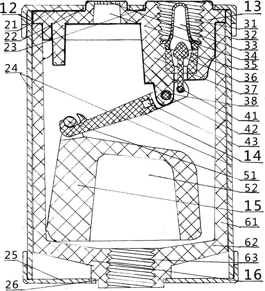
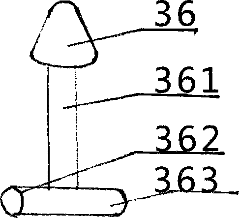
[0021] see Figure 1-Figure 6 , make protective cover (21), protective pipe (24), bottom protection (25) with punching press, method of pulling gold. The valve body (13), the valve handle (14), the floating body (15), the liquid reservoir (16), the strainer pipe (32), and the valve port (35) are made of non-toxic, heat-resistant and frost-resistant high-quality material by injection molding and glue pressing , valve plug (36), valve handle cover (431), and strictly check the quality of each accessory. Put the valve port (35) and valve plug (36) into the valve body (13), the shaft (42) of the valve handle (14) extends into the shaft hole (38), and the right end of the plug shaft (362) is inserted into the head hole (41) , the cover head hole (432) is set on the left end of the plug rotating shaft (363), the cover rotating shaft hole (433) is positioned and connected with the rotating shaft (42) head, the cover double hook (434) is fixedly connected with the double hook hole (4...


PUM


Abstract

The invention provides an overflow-free internally piloted valve and an installation method. The overflow-free internally piloted valve is a liquid level internally piloted device. The overflow-free internally piloted valve is mainly characterized in that a protective cover is arranged outside the internally piloted valve for protection, the internally piloted valve is internally provided with a conic valve port and a valve plug, the valve is closed tightly through the pressure of tap water, and therefore the valve can be operated for a long time without deformation; the distance between a head hole of a valve handle and a rotary shaft is short and the lever effect is large; suspended matter is manufactured into a floating body and is heavy after being dewatered and capable of floating on water and free of expansion or deformation, and a large floating ball is not needed for closing the valve; and a filter net pipe and a filter net are arranged so as to prevent impurities and winged insects from entering the valve. Due to the fact that the internally piloted valve is accurately opened and closed and is durable and proper in shape, the internally piloted valve can be installed at the front portion, the rear portion, the left portion, the right portion, the outer side, the inner side, the near portion and the far portion of a solar water tank or other water tanks or heat storage devices, spaces are reserved for the water tanks and the heat storage devices, and liquid cannot overflow even when the liquid expands.

Description

technical field [0001] The invention relates to a non-spill automatic control valve in the field of automatic liquid level control. Background technique [0002] When the solar water heater (hereinafter referred to as the sun heater) is filled with water, many users manually or automatically fill the water tank of the sun heater to a high level, even higher than the water tank, but when the sun heater produces heat, the water expands, so it will Form overflow water, make much hot water lose in vain. There is an electronic self-control valve, which can use sensors to display the temperature and liquid level of the water in the solar heater, and control the water at the set liquid level, but its mechanism is complex, expensive, fragile, and must be controlled by electricity; there is a mechanical Type self-control valve, the strip-shaped floating pipe extends into the water tank through the vent hole on the side of the anode heater, and the self-control valve body is plugged ...

Claims


Application Information

Patent Timeline
Patent Type & Authority Applications(China)
IPC IPC(8): F16K31/24F16K27/12F24J2/46
CPCY02E10/40F16K31/24F16K27/12F24S80/00
Inventor 朱科锋
Owner 朱科锋
Learn More