Intelligent household electrical appliance safe rotation base of intelligent home system
A technology of smart home system and swivel seat, which is applied in the direction of supporting machines, mechanical equipment, machine tables/supports, etc. It can solve the problems of poor safety, non-detachable, inconvenient cleaning and replacing parts, etc., and achieves convenient components and easy loading and unloading , the effect of avoiding safety accidents
- Summary
- Abstract
- Description
- Claims
- Application Information
AI Technical Summary
Problems solved by technology
Method used
Image

Examples
Embodiment 1
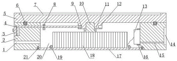
[0016] see figure 1 , the smart home appliance safety rotating seat of the smart home system, including a fixed seat 2 and a rotating disk 5 installed on the upper end of the fixed seat 2, the middle part of the fixed seat 2 is provided with an installation cavity 20 with upper and lower openings, and the bottom of the installation cavity 20 is passed through the sink. The hole screw 21 is connected with the mounting base 17, the bottom of the mounting base 17 is on the same plane as the bottom of the fixing base 2, the middle part of the upper end of the mounting base 17 is connected with the brake motor 18 through the fixing screw 19, and the lower end of the middle part of the rotating disk 5 is provided with a cylinder Shaped positioning platform 12, the rotating shaft 10 of the brake motor 18 is flexibly connected with the positioning platform 12, the side of the installation cavity 20 is also clamped with the controller 13 by the buckle 16, and the outer side of the fixed...
Embodiment 2
[0022] This embodiment adds the following structure on the basis of Embodiment 1: the movable rod 4 is also threadedly connected with a retaining ring 8, the retaining ring 8 is located in the installation cavity 20 and the diameter of the retaining ring 8 is greater than the diameter of the movable rod 4 .
[0023] The stop ring 8 of this embodiment can be stuck on the side wall of the installation cavity 20, preventing the movable rod 4 from being pulled out and affecting the use, and can also reduce the trouble of repositioning by the user, and can also avoid loss during transportation. The movable rod 4 is threaded, and is also convenient for dismounting.
Embodiment 3
[0025] In this embodiment, the following structure is added on the basis of embodiment 1 or embodiment 2: a ring of balls 6 is also arranged on the contact surface between the fixed base 2 and the rotating disk 3 .
[0026] In this embodiment, the rotating disk 5 rubs against the contact surface of the fixed seat 2 when rotating, which not only increases the resistance, but also increases energy consumption. At the same time, the fixed seat 2 and the rotating disk 5 are also easy to wear and cannot be used for a long time. Therefore, this embodiment For example, a circle of balls 6 is also arranged on the horizontal contact surface of the fixed seat 2 and the rotating disk 5. When the fixed seat 2 and the rotating disk 5 rotate relative to each other, the balls 6 replace the friction between the two, and the static friction is converted into sliding friction, which reduces the friction. Friction prolongs the life of both.
PUM
 Abstract
Description
Claims
Application Information
 - R&D Engineer
- R&D Manager
- IP Professional
- Industry Leading Data Capabilities
- Powerful AI technology
- Patent DNA Extraction
Browse by: Latest US Patents, China's latest patents, Technical Efficacy Thesaurus, Application Domain, Technology Topic.
© 2024 PatSnap. All rights reserved.Legal|Privacy policy|Modern Slavery Act Transparency Statement|Sitemap