Wind direction adjusting device of air conditioner and air conditioner

A technology for adjusting devices and air conditioners, which is applied to air conditioning systems, space heating and ventilation, space heating and ventilation details, etc., and can solve the problems of increased component management load, complicated manufacturing process and assembly process, and complicated manufacturing process etc. to achieve the effects of lightening the management load, simplifying the manufacturing process and assembly process

Active Publication Date: 2018-06-26
MITSUBISHI ELECTRIC CORP
View PDF4 Cites 0 Cited by
  • Summary
  • Abstract
  • Description
  • Claims
  • Application Information

AI Technical Summary

Problems solved by technology

[0004] However, the airflow direction adjusting device described in Patent Document 1 is composed of an airflow direction adjusting member having a movable operation part and an airflow direction adjusting member not having a movable operating part. Since these are formed in different structures, the manufacturing process and assembly process are complicated. , and the management load of the components increases
For example, in the assembly process, it is necessary to select and install which wind direction adjustment part to install where, so the manufacturing process is complicated

Method used


Image

  • Wind direction adjusting device of air conditioner and air conditioner
  • Wind direction adjusting device of air conditioner and air conditioner
  • Wind direction adjusting device of air conditioner and air conditioner

Examples


Embodiment approach 1

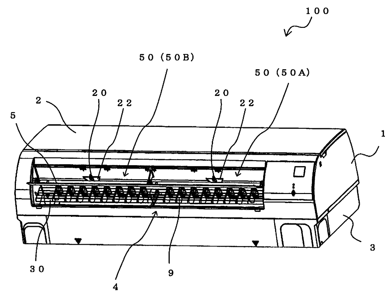
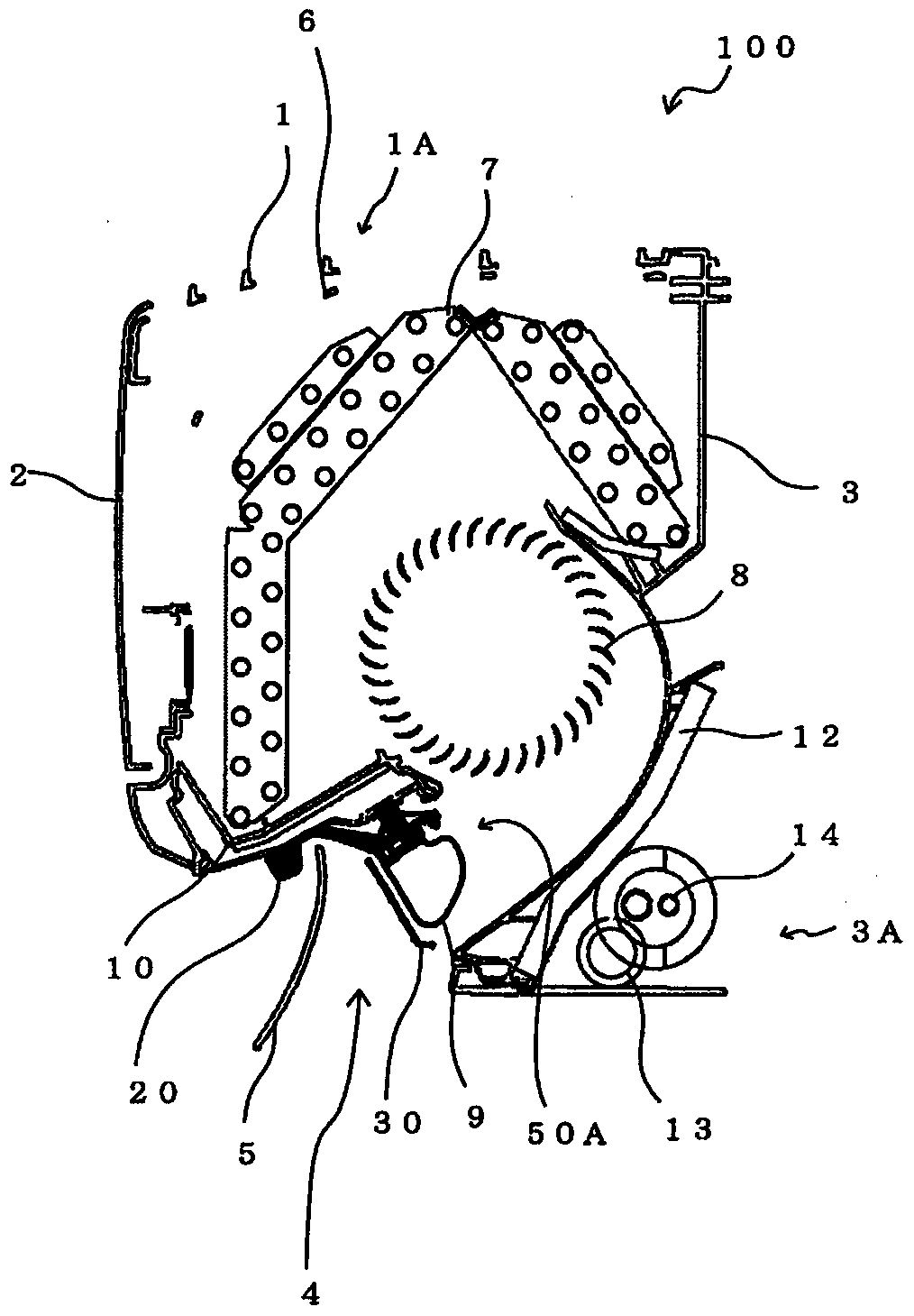
[0033] figure 1 It is a perspective view of the indoor unit 100 of the air conditioner according to Embodiment 1 of the present invention. figure 2 is schematically shown figure 1 A longitudinal sectional view of a longitudinal section of the indoor unit 100 is shown. The indoor unit 100 according to this embodiment is attached to, for example, an indoor wall or the like, and performs indoor cooling or heating.

[0034] The indoor unit 100 includes a front housing 1 and a rear housing 3 . The rear housing 3 is attached to an installation member (not shown), and supports the entire indoor unit 100, and the installation member is fixed to a wall or a column or the like. The front housing 1 is assembled to the rear housing 3, and the front design panel 2 that covers the front surface of the indoor unit 100 is attached to the front surface of the front housing 1 in a freely openable and closable manner. The front pattern design panel 2 is, for example, rotatably attached to t...

Embodiment approach 2

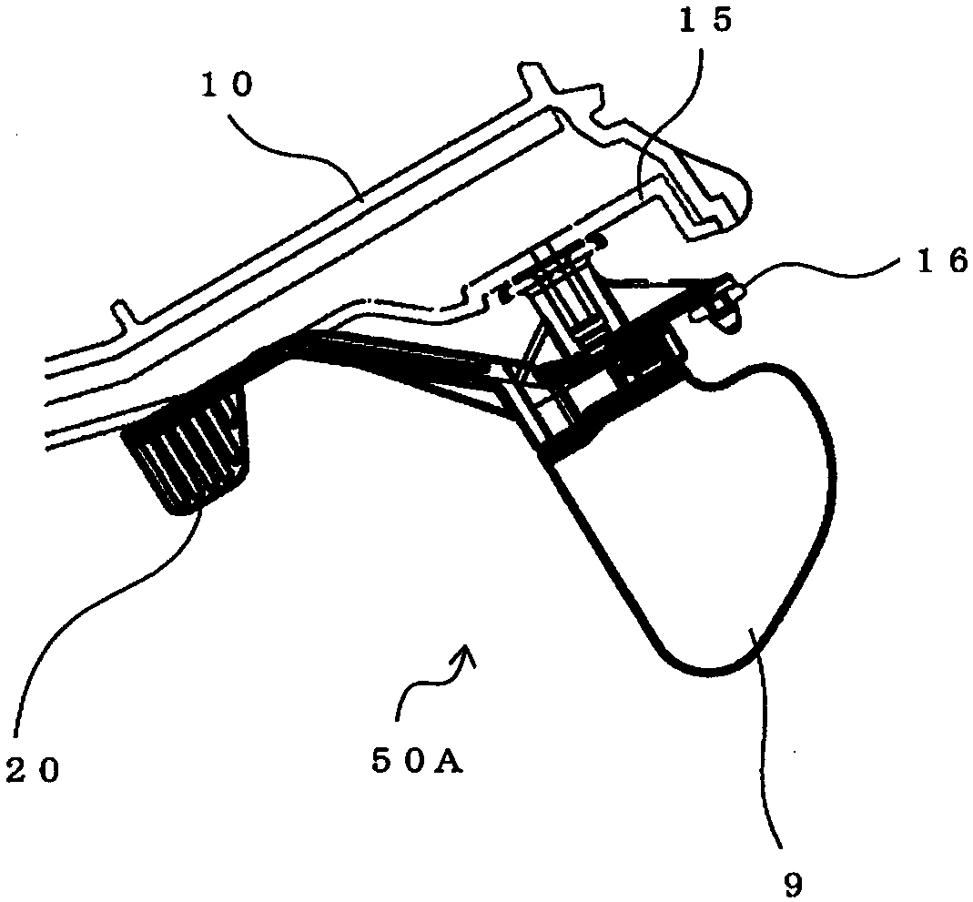
[0061] In Embodiment 1 mentioned above, the example which rotates the airflow direction adjustment member 9 by operating the manual operation member 20 attached to the airflow direction adjustment member 9 was demonstrated. Compared with Embodiment 1, in the wind direction adjusting device 50C according to Embodiment 2, the manual operation member 20 is omitted, and the plurality of wind direction adjusting members 9 connected by the link plate 16 are automatically rotated by the drive mechanism (drive unit) 40 . In the following description, the description of the part overlapping with Embodiment 1 is omitted.

[0062] Figure 13 It is a schematic diagram of a part of wind direction adjusting device 50C according to Embodiment 2 of the present invention. In this embodiment, a drive mechanism 40 (not shown) is connected to at least one of the ends in the longitudinal direction of the link plate 16A. The drive mechanism 40 moves the link plate 16A substantially in the longit...


PUM


Abstract

[Object] To provide an air flow direction adjusting device of an air-conditioning apparatus including commonalized air flow direction adjusting members. [Solution] An air flow direction adjusting device of an air-conditioning apparatus includes: a base member 15 including a plurality of attachment shafts 19 projecting from an air passage surface forming an air passage of the air-conditioning apparatus; a plurality of air flow direction adjusting members 9 individually attached to the attachment shafts 19 such that the plurality of air flow direction adjusting members 9 are allowed to rotate; and a link plate 16 configured to connect the plurality of air flow direction adjusting members 9 to one another such that the plurality of air flow direction adjusting members 9 rotate in an interlocked manner. At least one of the plurality of air flow direction adjusting members 9 includes a rotation shaft attachment portion 91 attached to the corresponding one of the attachment shafts 19, a link plate engagement portion 92 to be engaged with the link plate 16, and an operation member attachment portion 93 to which a manual operation member 20 for manually adjusting orientation of the air flow direction adjusting members 9 is attached. The manual operation member 20 is not attached to at least one of the air flow direction adjusting members 9.

Description

technical field [0001] The invention relates to a wind direction adjusting device of an air conditioner and the air conditioner. Background technique [0002] Conventionally, there is known an airflow direction adjusting device that provides a plurality of airflow direction adjusting members at an airflow outlet of an air conditioner to change the direction of air blown out from the airflow outlet of the air conditioner. For example, in the airflow direction adjustment device described in the following patent document 1, it is configured to include an airflow direction adjustment member with a movable operation part and an airflow direction adjustment member without a movable operation part. By operating the movable operation part, multiple The direction of the wind direction adjusting member is adjusted to adjust the direction of the wind blown out from the air outlet of the air conditioner. [0003] Patent Document 1: Japanese Patent Application Laid-Open No. 9-196457 (pa...

Claims


Application Information

Patent Timeline
Patent Type & Authority Patents(China)
IPC IPC(8): F24F13/14
CPCF24F1/0011F24F13/1413F24F13/1426F24F13/1486F24F2013/1473
Inventor 尾崎田小嶋和仁大场安志大村纮史须贝将太新村卓也内藤洋辅
Owner MITSUBISHI ELECTRIC CORP
Why Eureka
Try Eureka