
High voltage vibrating wire strain gauge

A vibrating wire and strain gauge technology, which is applied to measuring devices, instruments, and the use of ultrasonic/sonic/infrasonic waves, etc., can solve the problem of low measurement stability and low measurement accuracy of vibrating wire strain gauges. Insufficient resistance to water pressure and other problems, to achieve the effect of maintaining the stability of the measured value and long-term adaptability, the stability of the measured value and the long-term reliability guarantee, and ensuring the long-term stability

Active Publication Date: 2017-09-15
NANJING NARI GROUP CORP +1
View PDF8 Cites 1 Cited by
  • Summary
  • Abstract
  • Description
  • Claims
  • Application Information

AI Technical Summary

Problems solved by technology

[0005] The purpose of the present invention is to provide a high-voltage-resistant vibrating wire strain gauge to solve the problems of low measurement stability of the vibrating wire strain gauge, low measurement accuracy and insufficient water pressure resistance of the vibrating wire strain gauge

Method used


Image

  • High voltage vibrating wire strain gauge
  • High voltage vibrating wire strain gauge
  • High voltage vibrating wire strain gauge

Examples


Embodiment Construction

[0016] The present invention will be described in further detail in conjunction with the accompanying drawings and specific embodiments.

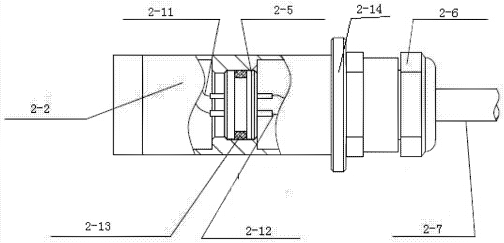
[0017] Such as figure 2 As shown, the high-voltage vibrating wire strain gauge of the present invention includes a cable joint 2-6, a cable 2-7, a left flange 2-1, a right flange 2-14, and is placed between the left and right flanges. Protective shell 2-2, measuring device 2-3 placed inside the protective shell 2-2, right end fixed end 2-4, partition joint 2-5, steel string 2-10 and steel string protective pipe 2-8 .

[0018] Among them, the steel string 2-10 is stretched inside the steel string protection tube 2-8, and fixed on the left flange 2-1 and the right fixed end 2-4, and the right fixed end 2-4 is mainly used for fixing The other end of the steel string 2-10, its main function is to cooperate with the left flange 2-1 to jointly fix and tension the steel string 2-10, between the right fixed end 2-4 and the protective shell 2-2 ...


PUM


Abstract

The invention discloses a high pressure-resistant vibrating wire strain gauge comprising a cable joint, a cable, left and right flanges, a protection shell arranged between the left and right flanges, and a measuring device, a right fixed end, a partition joint, a steel wire and a steel wire protection tube which are arranged inside the protection shell. The steel wire is stretched and drawn in the steel wire protection tube, and is fixed to the left flange and the right fixed end. The measuring device is fixed to the steel wire protection tube by an injection mold. The measuring device, the steel wire, the steel wire protection tube, the left flange and the right fixed end form an integrated string core sensitive component. The integrated string core sensitive component is disposed inside the protection shell and completely isolated from the outside to ensure reliable resistance to water pressure. The partition joint is disposed in a cavity between the right fixed end and the right flange to play an isolation role. The water pressure resistance of the high pressure-resistant vibrating wire strain gauge of the invention is improved greatly, and the value measurement stability is improved significantly.

Description

technical field [0001] The invention relates to a high-voltage-resistant vibrating wire strain gauge, which belongs to the technical field of strain measurement devices. Background technique [0002] High-voltage vibrating wire strain gauges are mainly used to monitor the strain of geotechnical engineering and other concrete buildings, and are suitable for long-term buried in hydraulic buildings or other buildings to measure the strain inside structures. Due to the special use environment, most of them are installed underwater and measured for a long time. Therefore, the instrument itself needs to have the ability to withstand large water pressure, especially in large-scale pumped storage power stations, the strain gauges buried inside the dam body The water pressure it bears is relatively high, and in the case of water flow impact, the water pressure may reach more than 3MPa. Therefore, higher requirements are put forward for the water pressure resistance of the vibrating w...

Claims


Application Information

Patent Timeline
IPC IPC(8): G01B17/04
CPCG01B17/04
Inventor 夏明郑水华刘果吕刚李杰廖占勇崔岗
Owner NANJING NARI GROUP CORP
Learn More