Supercharge Your Innovation With Domain-Expert AI Agents!

Automatic focusing method of pushbroom imaging spectrometer

An imaging spectrometer and automatic focusing technology, applied in the field of spectral remote sensing imaging, can solve the problem of too long focusing time, achieve the effect of clear performance, ensure accuracy, and avoid too long focusing time

Inactive Publication Date: 2015-11-25
SICHUAN DUALIX SPECTRAL IMAGING TECHNOLOGY CO LTD
View PDF8 Cites 6 Cited by
  • Summary
  • Abstract
  • Description
  • Claims
  • Application Information

AI Technical Summary

Problems solved by technology

[0008] The present invention overcomes the deficiencies of the prior art and provides an automatic focusing method for a push-broom imaging spectrometer, which avoids the problem that the captured image is not accurate and clear due to too long focusing time or inaccurate debugging focus

Method used


Image

  • Automatic focusing method of pushbroom imaging spectrometer
  • Automatic focusing method of pushbroom imaging spectrometer
  • Automatic focusing method of pushbroom imaging spectrometer

Examples


Embodiment 1

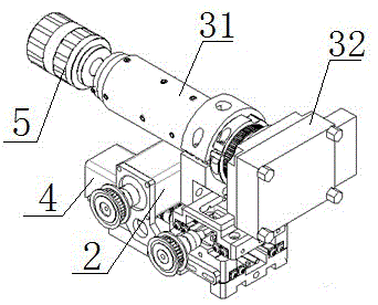
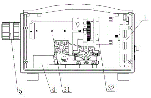
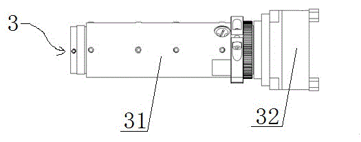
[0028] Such as figure 1 , figure 2 , image 3 A push-broom imaging spectrometer shown, its automatic focusing method is:

[0029] First, the controller 1 controls the operation of the scanning motor 2, and the scanning motor 2 drives the imaging module 3 to move to the set position in a direction perpendicular to the optical axis through the adapter, thereby determining the exposure time required by the area array detector 32. In this implementation For example, the set position is set as the position where the slit of the imaging spectrometer 31 faces the center of the lens; secondly, the controller 1 controls the operation of the scanning motor 2, and the scanning motor 2 drives the imaging module 3 through the adapter along the vertical direction The direction of the optical axis moves to a set position for automatic focusing. The set position can be the position where the slit of the imaging spectrometer 31 faces the center of the lens or other positions convenient for ...

Embodiment 2

[0034] This embodiment has been further improved on the basis of embodiment 1, as figure 1 , figure 2 , image 3 As shown in a push-broom imaging spectrometer, the focusing motor 4 drives the imaging module 3 from the initial position through the adapter, and moves toward the lens 5 along the optical axis, and walks through the design with a larger step size. The full stroke of this design is 1.2cm, and the time it takes to complete the autofocus process is 1~5s. It avoids the increase of focusing time due to too long full stroke, and also avoids the problem that the ideal focus is not within the stroke range due to too short full stroke.

Embodiment 4

[0036] This embodiment has been further improved on the basis of embodiment 1, as figure 1 , figure 2 , image 3 In the shown push-broom imaging spectrometer, the starting position in the first step is the position where the imaging module is located when the distance between the lens and the imaging module is the farthest. This makes it easy to set the control program of the focusing motor 4, saving manpower and material resources.


PUM


Abstract

The present invention provides an automatic focusing method of a pushbroom imaging spectrometer, wherein the pushbroom imaging spectrometer comprises a controller, a scanning motor, an imaging module, an imaging spectrometer, an area-array detector, a focusing motor and a lens. Firstly, the imaging module is moved driven by the scanning motor, and the time of exposure required by the area-array detector is determined; and secondly, the imaging module is subjected to repeat research driven by the focusing motor until the step size of the focusing motor is reduced to a setting value, the research is end, and the focus is determined. According to the invention, the focus may be quickly and accurately determined to make the imaging module in an ideal focus state, the captured images are clear and the details of the images are rich so as to improve the space resolution and the spectral resolution of the system, and at the same time the problem of an overlong focusing time is avoided so as to ensure the accuracy of the pushbroom imaging spectrometer for capturing the shooting objects.

Description

technical field [0001] The invention relates to the technical field of spectral remote sensing imaging, in particular to an automatic focusing method of a push-broom imaging spectrometer. Background technique [0002] The development of remote sensing technology has gone through panchromatic (black and white), color photography, and multi-spectral scanning imaging stages. The imaging spectrum technology that appeared in the early 1980s brought optical remote sensing into a new stage—the stage of hyperspectral remote sensing. The so-called hyperspectral remote sensing refers to the remote sensing science and technology with high spectral resolution. The imaging spectrometer used in the imaging spectroscopy technology can acquire many very narrow and continuous spectrum in the ultraviolet, visible, near-infrared and short-wave infrared regions of the electromagnetic spectrum. image data. Imaging spectrometers provide each pixel with dozens to hundreds of narrow-band spectral ...

Claims


Application Information

Patent Timeline
Patent Type & Authority Applications(China)
IPC IPC(8): G01J3/02
Inventor 陈兴海刘业林曹佳宝张卓
Owner SICHUAN DUALIX SPECTRAL IMAGING TECHNOLOGY CO LTD
Features
  • R&D
  • Intellectual Property
  • Life Sciences
  • Materials
  • Tech Scout
  • Unparalleled Data Quality
  • Higher Quality Content
  • 60% Fewer Hallucinations
Learn More