Torque sensor mounting structure

A technology of torque sensor and transition plate, which is applied in the direction of instruments, measuring devices, torque measurement, etc., can solve the problems of time-consuming and low efficiency, achieve accurate measurement, protect the safety of workers, and avoid the reduction of installation accuracy

Active Publication Date: 2015-11-25
杭州奔月科技有限公司
View PDF4 Cites 4 Cited by
  • Summary
  • Abstract
  • Description
  • Claims
  • Application Information

AI Technical Summary

Problems solved by technology

The conventional method of replacing the torque sensor requires disassembly and installation of the existing torque sensor and the small-range high-precision torque sensor, resulting in long time-consuming and low efficiency

Method used


Image

  • Torque sensor mounting structure
  • Torque sensor mounting structure
  • Torque sensor mounting structure

Examples


Embodiment Construction

[0018] The present invention will be further described below in conjunction with the accompanying drawings and specific embodiments.

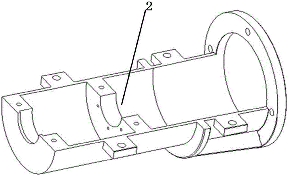
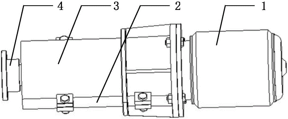
[0019] like Figure 1~5 As shown, a torque sensor installation structure includes a shell, a load end sleeve flange 4, a coupling 5, a flanged torque sensor 6, a transition plate 7, a transition plate end sleeve flange 8, and a bearing seat Ⅰ9, sleeve Ⅰ10, double round nut Ⅰ11, axial torque sensor 12, double round nut Ⅱ13, sleeve Ⅱ14, bearing seat Ⅱ15, bearing Ⅰ16, bearing Ⅱ17, shaft end retaining ring 18, screw 19, flat key Ⅰ20, flat Key II 21.

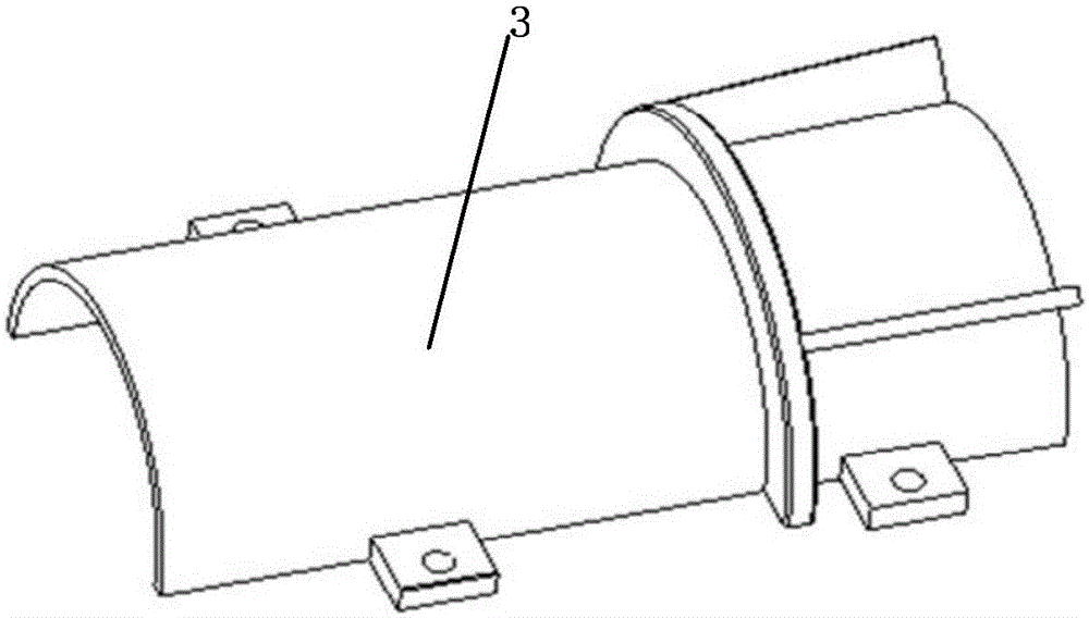
[0020] The housing includes a bracket 2 and an upper case 3. Two protrusions are provided at the connection between the bracket 2 and the upper case 3. The protrusions are provided with connecting threaded holes for fixing the upper case 3 on the bracket 2. Upper: A section of sleeve flange 4 at the load end, coupling 5, flanged torque sensor 6, transition plate 7, sleeve flange 8 at the end of the ...


PUM


Abstract

The invention discloses a torque sensor mounting structure. The torque sensor mounting structure comprises a housing, a load end sleeve flange, a shaft coupling, a flange torque sensor, a transition disk, a transition disk end sleeve flange, bearing pedestals, sleeves, double circular nuts, a shaft torque sensor, bearings, a shaft end back-up ring and flat keys. The housing comprises a support and an upper cover casing, wherein two bulges are formed at the joint of the support and the upper cover casing; and a connection screwed hole is formed in each bulge. An output shaft of a motor is connected with one end of the flange torque sensor through the shaft coupling, and the other end of the flange torque sensor is connected with the transition disk end sleeve flange through the transition disk; the transition disk end sleeve sensor is connected with one end of the shaft torque sensor through one of the two flat keys; and the other end of the shaft torque sensor is connected with the load end sleeve flange through the other flat key. For the torque sensor mounting structure, the rigidity and the operation stability of the mounting structure are improved, and the mounting structure can prevent mounting and dismounting operation of a current flange torque sensor so that the efficiency is improved.

Description

technical field [0001] The invention belongs to the technical field of mechanical structures, and in particular relates to a structure for adding a torque sensor, in particular to a structure for installing a shaft-type torque sensor between an existing flange-type torque sensor and a load. Background technique [0002] In the automobile bench test technology, the electric motor is widely used as the prime mover. During the operation of the automobile test bench, the output shaft end of the motor is connected to the coupling and then connected to the load to realize the transmission of torque from the motor to the load. When measuring the torque at the output end of the motor, a torque sensor must be installed between the coupling and the load, and its range meets the measurement requirements for the torque at the output end of the motor for all tests. In this way, when conducting a test that requires the motor to output a large torque, the existing torque sensor can provid...

Claims


Application Information

Patent Timeline
Patent Type & Authority Applications(China)
IPC IPC(8): G01L3/00
Inventor 周晓军林卫军吴思源陈嘉迪杨勇
Owner 杭州奔月科技有限公司
Why Eureka
Try Eureka