
In-mold hydraulic drive mechanism of an injection mold

A technology of injection mold and driving mechanism, applied in the field of hydraulic driving mechanism in injection mold, can solve the problems of small internal space of mold and inability to use conventional hydraulic cylinder, etc., and achieve the effect of easy maintenance, saving production energy, and saving mold space.

Active Publication Date: 2017-07-14
宏利科技(苏州)有限公司
View PDF6 Cites 0 Cited by
  • Summary
  • Abstract
  • Description
  • Claims
  • Application Information

AI Technical Summary

Problems solved by technology

[0008] The main technical problem to be solved by the present invention is to provide a hydraulic drive mechanism in the injection mold, which can solve the problem that the conventional hydraulic cylinder cannot be used due to the small internal space of the current mold.

Method used


Image

  • In-mold hydraulic drive mechanism of an injection mold
  • In-mold hydraulic drive mechanism of an injection mold

Examples


Embodiment Construction

[0021] The preferred embodiments of the present invention will be described in detail below in conjunction with the accompanying drawings, so that the advantages and features of the present invention can be more easily understood by those skilled in the art, so as to define the protection scope of the present invention more clearly.

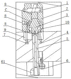
[0022] see figure 1 , the embodiment of the present invention includes:

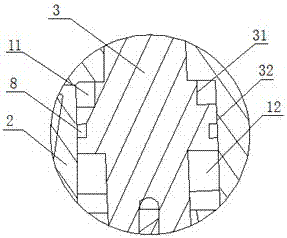
[0023] An in-mold hydraulic drive mechanism of an injection mold, comprising: a mold (not marked in the figure), a cylinder body 2, a piston rod driving device 3 and a rear end cover 9, the cylinder body 2 is arranged inside the mold and integrated with the mold structure, the upper end of the cylinder body 2 is provided with a slider 1, the rear part of the slider 1 is provided with a slanted hole, the cylinder body is provided with an oil chamber 10, and the front end of the piston rod driving device 3 is designed as The form of the bent pin and the inclined surface of t...


PUM


Abstract

The invention discloses an in-mold hydraulic drive mechanism of an injection mold, comprising: a mold, a cylinder body, a piston rod driving device and a rear end cover. The cylinder body is arranged inside the mold and has an integrated structure with the mold. The upper end of the slider is provided with a slider, the rear part of the slider is provided with a slanted hole with a rectangular cross section, the cylinder is provided with an oil chamber, the front end of the piston rod driving device is designed in the form of a bent pin and the The inclined surface of the bent pin matches the inclined surface of the inclined hole of the slider, and the part of the piston rod driving device in the oil chamber is stepped, and it has at least one step, wherein the outer diameter of the largest step is the same as the inner diameter of the oil chamber, The piston rod driving device can reciprocate up and down in the oil chamber and drive the slider to move laterally through the bent pin at the front end. Two oil passages are opened in the mold to connect the upper chamber and the lower chamber of the oil chamber respectively. The invention can solve the problem that conventional hydraulic cylinders cannot be used due to the small internal space of the current mold.

Description

technical field [0001] The invention relates to the field of injection molding, in particular to an in-mold hydraulic drive mechanism of an injection mold. Background technique [0002] The hydraulic drive system currently used in the mold industry is mainly a standard hydraulic cylinder system purchased from some hydraulic equipment manufacturers, which is connected with the parts that need to be driven by the mold through threads or hangers according to requirements. The hydraulic cylinder part is composed of cylinder body, piston, seal, front and rear end caps and connecting rods. [0003] In the design of injection molds, there are many side core-pulling structures (we usually call them sliders), for those sliders with large core-pulling area and long core-pulling distance. Hydraulic cylinders are usually used to drive in mold design. However, with the continuous optimization and improvement of product design, the design of conventional hydraulic cylinder drive shows t...

Claims


Application Information

Patent Timeline
Patent Type & Authority Patents(China)
IPC IPC(8): B29C45/33
CPCB29C45/332
Inventor 岑明平
Owner 宏利科技(苏州)有限公司
Learn More