Card removing device and portable electronic device using same
A technology for electronic devices and card devices, which is applied to parts, coupling devices, circuits, etc. of connection devices, can solve the problems of troublesome chip card removal process, and achieve the effects of simple structure, time saving, and simple and fast operation.
- Summary
- Abstract
- Description
- Claims
- Application Information
AI Technical Summary
Problems solved by technology
Method used
Image

Examples
Embodiment Construction
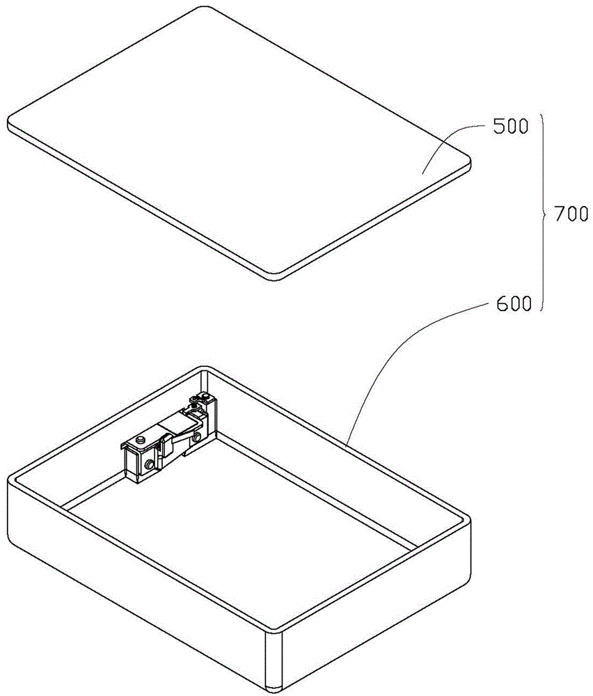
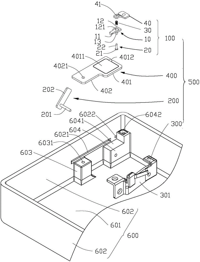
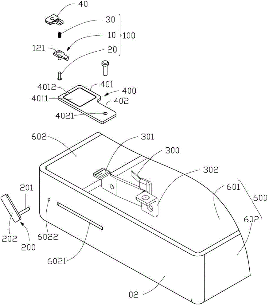
[0014] see Figure 1 to Figure 3 , the card removal device 500 according to the preferred embodiment of the present invention is used to remove the chip card (not shown) of the portable electronic device 700 (such as mobile phone, tablet computer, etc.). The portable electronic device 700 includes a casing 600 . The card removal device 500 includes a card tray 400 rotatably assembled in the accommodation space (not shown) formed by the housing 600 for loading a chip card, and used to lock the card tray 400 in the housing 600 The locking assembly 100 , the unlocking member 200 for unlocking the locking assembly 100 , and the elastic plate 300 abutting against the card tray 400 and pushing the card tray 400 to rotate and extend out of the casing 600 .
[0015] see further figure 2 and image 3 , the housing 600 has a bottom wall 601 and a plurality of side walls 602 perpendicular to the bottom wall 601 . One sidewall 602 defines a card insertion hole 6021 and an unlocking h...
PUM
 Abstract
Description
Claims
Application Information
 - Generate Ideas
- Intellectual Property
- Life Sciences
- Materials
- Tech Scout
- Unparalleled Data Quality
- Higher Quality Content
- 60% Fewer Hallucinations
Browse by: Latest US Patents, China's latest patents, Technical Efficacy Thesaurus, Application Domain, Technology Topic, Popular Technical Reports.
© 2025 PatSnap. All rights reserved.Legal|Privacy policy|Modern Slavery Act Transparency Statement|Sitemap|About US| Contact US: help@patsnap.com