Frequency jittering control circuit and method

一种频率抖动、控制电路的技术,应用在电气元件、输出功率的转换装置、直流功率输入变换为直流功率输出等方向,能够解决大EMI滤波器件、EMI特性难满足、无法调整等问题,达到实现频率的抖动、改善EMI特性的效果

Active Publication Date: 2015-11-25
DELTA ELECTRONICS (SHANGHAI) CO LTD
View PDF5 Cites 3 Cited by
  • Summary
  • Abstract
  • Description
  • Claims
  • Application Information

AI Technical Summary

Problems solved by technology

[0003] However, since the electromagnetic interference (EMI) generated by the power supply device in the fixed frequency state is generally concentrated at integer multiples of the switching frequency, it is difficult for the EMI characteristics of the power supply device to meet the required standards, but It also leads to the need for larger EMI filter devices in power supply devices, which increases a lot of production costs
[0004] On the other hand, for the power supply device with frequency conversion control or pulse frequency modulation (pulse frequency modulation, PFM) in the critical mode state, the power supply device can operate in different frequency conversion modes, but the frequency variation in these modes depends on the input / Output voltage and other conditions, where when the input voltage is fixed and the output voltage is supplied to a fixed load, the switching frequency in the above mode will be fixed, and this also causes the EMI generated by the switching device to still be concentrated at the integer of the switching frequency Times
[0005] In view of the above situation, the existing technology cannot effectively improve the EMI characteristics of the power supply device, let alone make adjustments according to the actual input / output of the power supply device to effectively improve the EMI characteristics

Method used


Image

  • Frequency jittering control circuit and method
  • Frequency jittering control circuit and method
  • Frequency jittering control circuit and method

Examples


Embodiment Construction

[0051] The following is a detailed description of the embodiments with accompanying drawings, but the provided embodiments are not used to limit the scope of the present invention, and the description of the structure and operation is not used to limit the order of its execution, any structure recombined by components , the resulting devices with equal efficacy are all within the scope of the present invention. In addition, the drawings are for illustration purposes only and are not drawn to original scale. For ease of understanding, the same components will be described with the same symbols in the following description.

[0052] Unless otherwise specified, the terms used throughout the specification and claims generally have the ordinary meaning of each term as used in the art, in this disclosure and in the special context. Certain terms used to describe the present disclosure are discussed below or elsewhere in this specification to provide those skilled in the art with ad...


PUM


Abstract

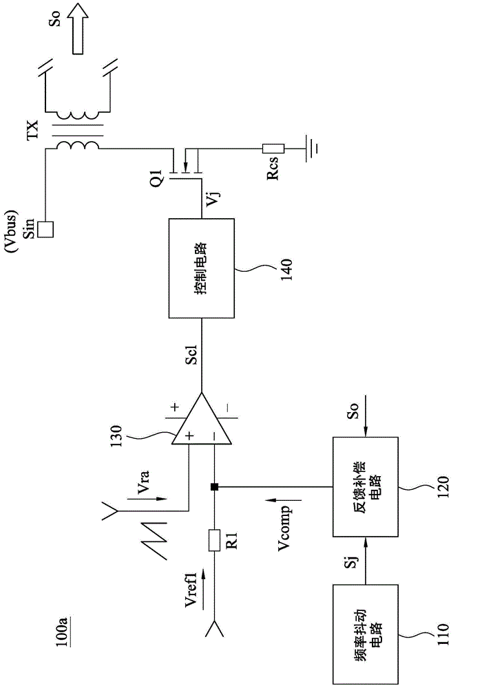
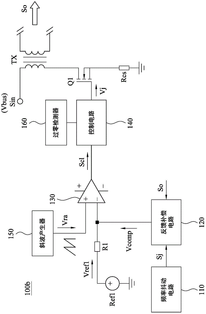
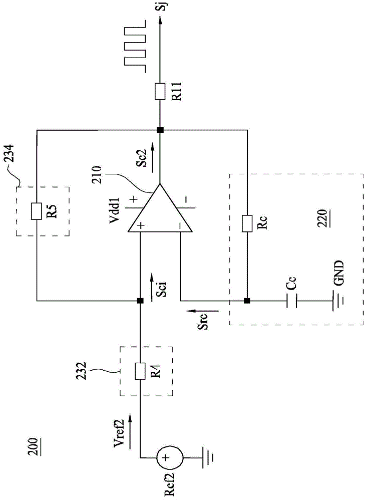
A frequency jittering control circuit includes a frequency jittering circuit, a feedback compensation circuit, a comparator and a control circuit. The frequency jittering circuit generates a frequency jittering signal. The feedback compensation circuit generates a feedback compensation signal in response to the frequency jittering signal and an output signal. The comparator outputs a comparison output signal according to the feedback compensation signal and an oscillation signal. The control circuit outputs a frequency jittering control signal for switching a main switch in a power supply apparatus, according to the comparison output signal, such that the power supply apparatus correspondingly generates the output signal.

Description

technical field [0001] The present disclosure relates to a power supply device, and in particular to a frequency jitter control mechanism in the power supply device. Background technique [0002] In existing power supply devices, the main switching devices controlled by the control chip generally operate at a fixed frequency, or in a critical mode where the frequency varies with input and output characteristics. [0003] However, since the electromagnetic interference (EMI) generated by the power supply device in the fixed frequency state is generally concentrated at integer multiples of the switching frequency, it is difficult for the EMI characteristics of the power supply device to meet the required standards, but It also leads to the need for a large EMI filter device in the power supply device, which increases a lot of manufacturing costs. [0004] On the other hand, for the power supply device with frequency conversion control or pulse frequency modulation (pulse freq...

Claims


Application Information

Patent Timeline
Patent Type & Authority Applications(China)
IPC IPC(8): H02M1/44
CPCH02M1/44H02M3/33523H02M2001/0025H02M1/0025H02M3/156H02M3/33507
Inventor 章兴华傅小平
Owner DELTA ELECTRONICS (SHANGHAI) CO LTD
Why Eureka
Try Eureka