Thermal superconducting sheet heat sink and manufacturing method thereof

A technology of superconducting sheet type and manufacturing method, which is applied in other manufacturing equipment/tools, manufacturing tools, cooling/ventilation/heating transformation, etc., and can solve the problem of complex liquid cooling radiator system, inability to meet heat dissipation requirements, and low efficiency of heat sink and other issues, to achieve the effect of convenient and flexible manufacturing, light weight and uniform heat distribution

Active Publication Date: 2018-04-17
ZHEJIANG JIAXI TECH CO LTD
View PDF9 Cites 1 Cited by
  • Summary
  • Abstract
  • Description
  • Claims
  • Application Information

AI Technical Summary

Problems solved by technology

[0007] In view of the shortcomings of the above-mentioned prior art, the purpose of the present invention is to provide a thermal superconducting fin radiator and its manufacturing method, which is used to solve the problem of the low efficiency of the radiator fins in the air-cooled radiator in the prior art, which cannot meet the requirements The problem of heat dissipation requirements and the complex system, high cost and safety risks of liquid-cooled radiators, etc., to greatly improve the fin efficiency and heat dissipation capacity of air-cooled radiators to meet the heat dissipation requirements of high-power modules

Method used


Image

  • Thermal superconducting sheet heat sink and manufacturing method thereof
  • Thermal superconducting sheet heat sink and manufacturing method thereof
  • Thermal superconducting sheet heat sink and manufacturing method thereof

Examples


Embodiment 1

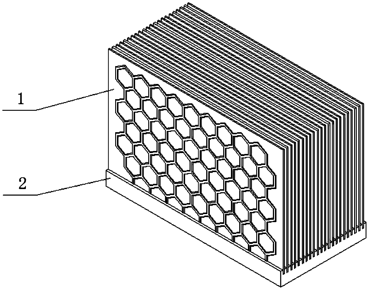
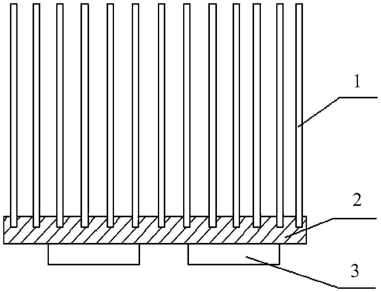
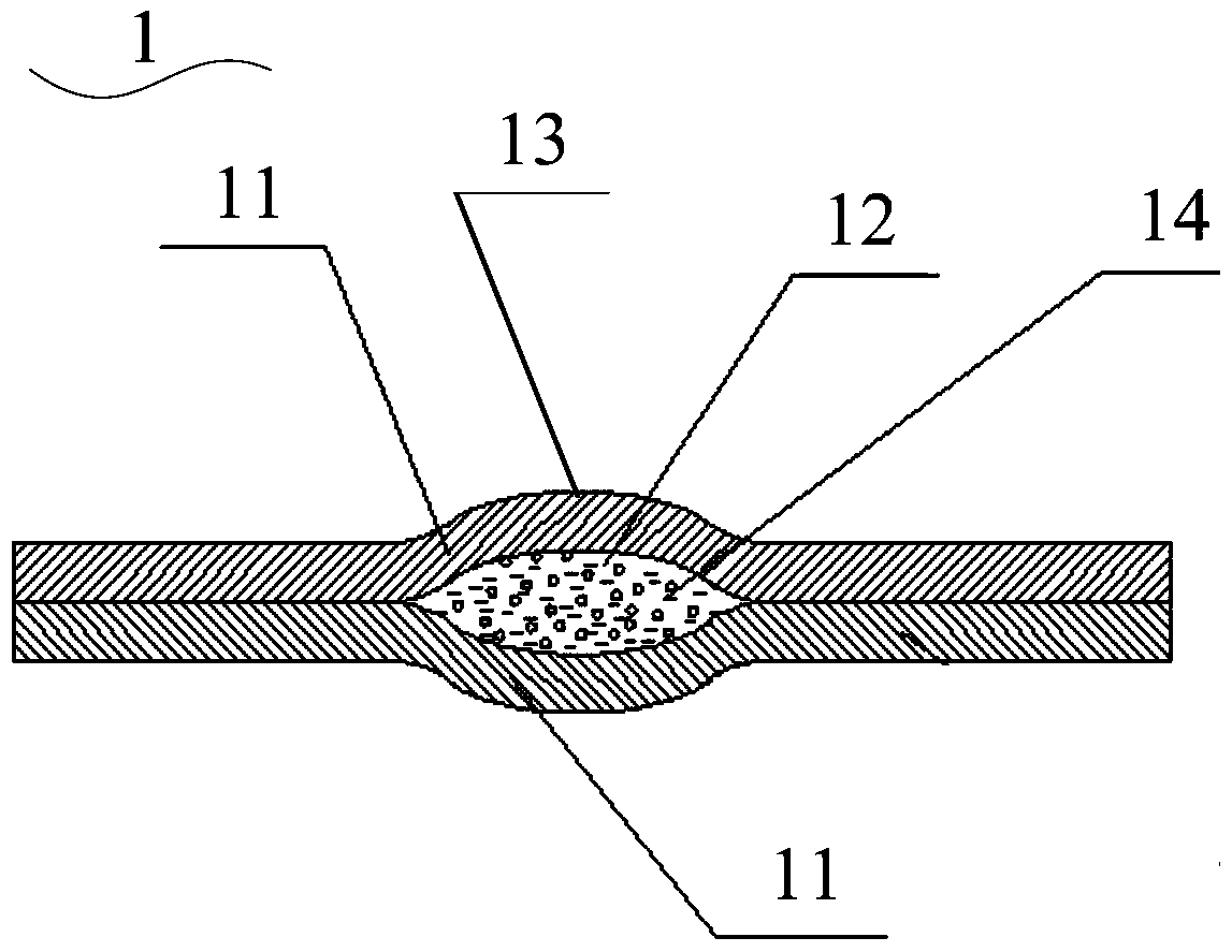
[0061] see Figure 1 to Figure 6 , the present invention provides a thermal superconducting fin radiator, the thermal superconducting fin radiator includes a radiator substrate 2 and a plurality of thermal superconducting fins 1 inserted on the radiator substrate 2; The thermal superconducting heat dissipation fin 1 includes two plates 11 that are composited together by a rolling process, and a closed pipe 12 that communicates with each other and has a certain structural shape is arranged between the two plates 11, and the closed pipe 12 It is filled with heat transfer working fluid 14 .

[0062] As an example, a groove (not shown) is provided on the heat sink substrate 2, and the side walls of the groove are perpendicular to the surface of the heat sink substrate 2; Vertically inserted into the groove, and the thermal superconducting fins 1 are fixedly connected to the heat sink substrate 2 through a mechanical extrusion process, a thermally conductive adhesive bonding proce...

Embodiment 2

[0075] see Figure 7 , the present invention also provides a thermal superconducting fin radiator, the structure of the thermal superconducting fin radiator described in this embodiment is roughly the same as that of the thermal superconducting fin radiator described in Embodiment 1, The difference between the two is: the thermal superconducting heat dissipation fins 1 in Embodiment 1 are vertically inserted into the heat sink substrate 2, while in this embodiment, the thermal superconducting heat dissipation fins 1 are obliquely inserted into the heat dissipation inside the device substrate 2.

[0076] As an example, the method of obliquely inserting the thermal superconducting heat dissipation fins 1 into the heat sink substrate 2 may be to first adopt the solution in Embodiment 1, and set a side wall on the heat sink substrate 2 perpendicular to the heat dissipation grooves on the surface of the device substrate 2, and insert the thermal superconducting fins 1 vertically i...

Embodiment 3

[0081] see Figure 8 , the present invention also provides a manufacturing method of a thermal superconducting fin radiator, the manufacturing method comprising:

[0082] S1: providing a heat sink substrate, and opening a groove on the heat sink substrate;

[0083] S2: The thermal superconducting heat dissipation fins are manufactured by the inflation process, and the closed pipes connected with each other and having a certain structural shape are formed inside the thermal superconducting heat dissipation fins, and a certain amount of heat transfer working fluid is filled in the closed pipes ;

[0084] S3: Insert one end of the thermal superconducting heat dissipation fin into the groove, and connect the thermal superconducting heat dissipation fin to the heat dissipation The device substrate is fixedly connected.

[0085] Execute step S1, see Figure 8 In the S1 step, a heat sink substrate is provided, and grooves are opened on the heat sink substrate.

[0086] As an exa...


PUM

PropertyMeasurementUnit
angleaaaaaaaaaa
angleaaaaaaaaaa

Abstract

The invention provides a thermal superconducting fin radiator and a manufacturing method thereof. The thermal superconducting fin radiator includes a radiator substrate and several thermal superconducting cooling fins inserted on the radiator substrate. By adopting thermal superconducting fins instead of conventional heat sinks in the prior art, the thermal superconducting fin radiator of the present invention has fast heat conduction, high fin efficiency, and unlimited height of the fins; the thermal superconducting fins of the present invention Chip radiators are easy and flexible to manufacture, low in cost, large in heat dissipation capacity, light in weight, and small in size. They can replace heat pipe radiators and some water-cooled radiators. They are especially suitable for the cooling needs of electronic devices with high power and high heat flux density, and have broad market prospects. and great economic value.

Description

technical field [0001] The invention relates to a radiator for heat dissipation of high-power electronic devices, in particular to a thermal superconducting sheet radiator and a manufacturing method thereof. Background technique [0002] Due to the rapid development of power electronics technology, the integration of high-power components such as IGBTs (insulated gate bipolar transistors), diodes, and thyristors is getting higher and higher, the power density is also increasing, and the heat generated during work is also increasing. bigger. In order to ensure the normal operation of power devices, the heat must be dissipated in a timely and effective manner. Because if the heat generated by the power device cannot be dissipated in time and quickly, the temperature of the chip in the power device will rise, which will cause a decrease in performance and shorten the service life, and will lead to the failure of the power device and the burning of the chip. Therefore, solving...

Claims


Application Information

Patent Timeline
Patent Type & Authority Patents(China)
IPC IPC(8): H05K7/20B23P15/26B23P23/04
Inventor 仝爱星
Owner ZHEJIANG JIAXI TECH CO LTD
Why Eureka
Try Eureka