Shock absorbing device for the front or rear structure of a vehicle

A technology for impact absorption and vehicles, applied in the substructure, vehicle components, transportation and packaging, etc., can solve the problems of reducing the aspect ratio, increasing the risk of buckling elastic instability, etc., and achieving the effect of reducing intrusion

Active Publication Date: 2015-11-25
CONSTELLIUM SINGEN +1
View PDF15 Cites 8 Cited by
  • Summary
  • Abstract
  • Description
  • Claims
  • Application Information

AI Technical Summary

Problems solved by technology

These new test conditions increase the risk of buckling-type elastic instability and lead to a further reduction of the aspect ratio so that

Method used


Image

  • Shock absorbing device for the front or rear structure of a vehicle
  • Shock absorbing device for the front or rear structure of a vehicle
  • Shock absorbing device for the front or rear structure of a vehicle

Examples


example 1

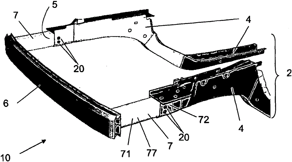
[0032] figure 2 The illustrated vehicle front structure includes an impact absorbing structure 10 according to an embodiment of the present invention. The frame 2 comprised by the structure has two longitudinal members 4 which jointly support a bumper beam 6 . The impact absorbing structure or CMS results from the assembly of said bumper beam and two absorbers 7 . The structure is positioned on the vehicle front structure such that each absorber is interposed between the longitudinal beam and said bumper beam.

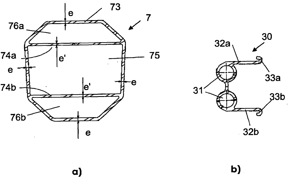
[0033] The absorber is a profile with one end integral with the bumper beam and the other end 72 inserted inside the open end of the side member 4 . This profile has what is hereafter referred to as the "useful part" 71 which is not inserted in the side member or the bumper beam and which is intended for crushing under the effect of a substantially frontal impact. The section of the profile is shown in image 3 on a. The cross-sectional area is 784mm 2 , the sec...

example 2

[0042] Figure 7 The vehicle front structure 10" shown in a comprises another embodiment of the impact-absorbing structure according to the present invention. The absorber 7" has one end integrated with the bumper beam 6" and the other end inserted into the side member 4". The open end is 5" inside the profile.

[0043] Figure 7 b shows the section of the profile. The area of ​​this section is 743mm 2 , the secondary axial moment of the section is about 90.1cm 4 . The radius of gyration ρ is close to 34.8mm. The material of the absorber is 6060T6 type. The length of the useful part is 200mm, so the aspect ratio is close to 5.7. With this geometry, the useful part of the absorber can be deformed by crimping when the impact occurs over a length of approximately 155 mm, approximately 4.5 times the radius of gyration.

[0044]The fixing conditions of the absorber 7" on the open end 5" of the stringer 4" are similar to those described in the previous example. The support s...


PUM

PropertyMeasurementUnit
Thicknessaaaaaaaaaa
Thicknessaaaaaaaaaa

Abstract

Shock absorbing structure (10, 10") for a vehicle comprising a side sill (2) comprising two chassis frame side members (4, 4") which together support a bumper beam (6, 6"), said shock absorbing structure comprising said bumper beam and an absorber (7, 7") interposed between each chassis frame side member and said bumper beam, said absorber having a working part (71) intended to deform in the event of an impact under the effect of a load below the limit load beyond which said chassis frame side member undergoes plastic deformation, said absorber being a section piece of which one end (72) is inserted inside the open end (5, 5") of said chassis frame side member and fixed thereto, characterized in that said absorber is an extruded aluminium alloy section piece of which the part not inserted inside said chassis frame side member or inside said bumper beam, which corresponds to said working part, has a length greater than 5 times its radius of gyration defined by formula (I), where I is the quadratic moment and S the cross-sectional area of said section piece, said cross section being such that, under the effect of a substantially frontal impact, said working part is able to deform in crumpling over a length such that the longitudinal crush distance is greater than 4 times said radius of gyration.

Description

technical field [0001] The invention relates to an impact absorbing device for a front or rear structure of a motor vehicle. The vehicle front or rear structure includes a bracket that typically includes two rails for collectively supporting a bumper beam. Each side member is generally constructed of a part oriented along the longitudinal axis of the vehicle welded over its entire length, the front or rear end of said part serving to support said bumper beam, which is typically transversely oriented. In the impact-absorbing arrangement relating to the present invention, absorbers, also known as "crash boxes", are interposed between the end of each side member and the bumper beam to protect the support structure in the event of a low-velocity impact. According to prior art documents, the crash box is either a deformable and movable part of the front part of the longitudinal beam, or a deformable part connected with the beam of the bumper to form an impact-absorbing device for ...

Claims


Application Information

Patent Timeline
IPC IPC(8): B60R19/34B62D21/15F16F7/12
CPCB60R19/34B62D21/152F16F7/12
Inventor O·勒比费C·朗格A·廷F·科佩科F·考菲耶
Owner CONSTELLIUM SINGEN
Why Eureka
Try Eureka