Methods of Stabilizing the Clock Frequency of Microcontrollers

一种微控制器、时钟频率的技术,应用在输出稳定、功率的自动控制、具有存储的校准系数的设备等方向,达到减小电压依赖性、提高通信质量、减小温度依赖性的效果

Active Publication Date: 2018-01-19
ENDRESS HAUSER GMBH CO KG
View PDF5 Cites 0 Cited by
  • Summary
  • Abstract
  • Description
  • Claims
  • Application Information

AI Technical Summary

Problems solved by technology

The disadvantage in the case of known solutions is the additional cost caused by the additional clock crystal
In addition, clock crystals require additional space, a characteristic that is problematic in many field technologies - such as automation - due to the continued push to miniaturize sensors

Method used


Image

  • Methods of Stabilizing the Clock Frequency of Microcontrollers
  • Methods of Stabilizing the Clock Frequency of Microcontrollers
  • Methods of Stabilizing the Clock Frequency of Microcontrollers

Examples


Embodiment Construction

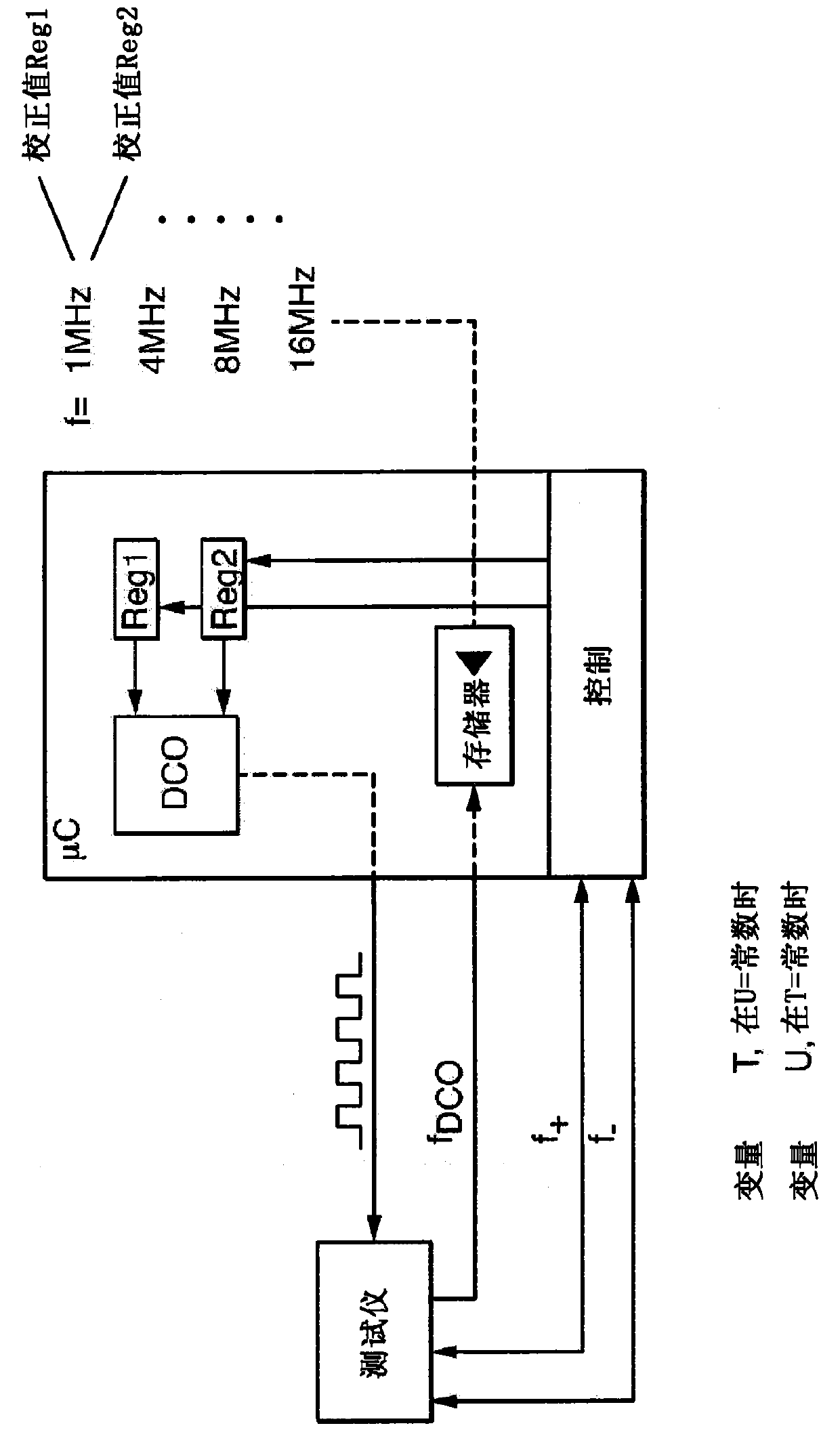
[0027] figure 1 A block diagram illustrating a first method for stabilizing the microcontroller μC clock frequency is shown. For this purpose, a defined clock frequency fDCO of the microcontroller μC is predetermined or determined at a defined temperature T1 of the microcontroller μC. In the illustrated case, the microcontroller μC is clocked via an adjustable oscillator DCO or an internal clock signal generator DCO, in particular a numerically controlled oscillator DCO. Via the adjustable oscillator DCO, different frequencies f can be set, here 1 MHz, 4 MHz, 8 MHz and 16 MHz.

[0028] A defined clock frequency fDCO (for example 1 MHz) of the microcontroller μC is supplied to a matching tester TESTER which is thermally insulated from the microcontroller μC. The microcontroller μC is then brought to a changed temperature T2 which deviates from the defined temperature T1 of the microcontroller μC. The change in the defined clock frequency fDCO caused by the temperature change...


PUM


Abstract

The invention relates to a method for stabilizing the clock frequency (f) of a microcontroller associated with a field device of automation technology, wherein the field device is exposed to different process conditions depending on the application, wherein at least two different The clock frequency (f) of the microcontroller (μC) is determined at temperature values ​​(T1, T2, etc.) and / or at least two different voltage values ​​(U1, U2, etc.). Based on the determined values, the dependence of the microcontroller (μC) clock frequency (f) on temperature (T) is determined within a predetermined temperature range and / or frequency range, and / or within a predetermined voltage range and / or frequency range , Microcontroller (μC) clock frequency (f) dependence on voltage (U). Storing the determined values ​​and, taking into account the determined temperature dependence and / or voltage dependence, at least approximately compensating for the influence of temperature (T) and / or voltage (U) on the microcontroller (μC) clock frequency (f) .

Description

technical field [0001] The invention relates to a method for stabilizing the clock frequency of a microcontroller associated with a field device of automation technology. The field device is preferably a sensor or an actuator for determining and / or monitoring at least one process variable. Sensors for process automation technology are produced and sold by the applicant in various embodiments. Background technique [0002] Sensors (and actuators) typically have at least two microcontrollers, where, for example, in the case of sensors, a process-side microcontroller is associated with the sensor component and a transmitter-side microcontroller is associated with the measurement transmitter . In general, measurement data representing process variables is transferred from the process-side microcontroller to the transmitter-side microcontroller, while most parameter data or sensor-specific identification data is transferred from the transmitter-side microcontroller to the proce...

Claims


Application Information

Patent Timeline
Patent Type & Authority Patents(China)
IPC IPC(8): G01D21/00H03L1/02G01D18/00
CPCG01D18/008G01D21/00H03L1/026H03L7/099G06F1/08
Inventor 卡伊·乌彭坎普沃尔特·龙巴赫佛朗哥·费拉多阿尔明·韦内特
Owner ENDRESS HAUSER GMBH CO KG
Why Eureka
Try Eureka