Negative-pressure indicating drainage bottle

A drainage bottle and indication technology, applied in the direction of suction containers, suction devices, hypodermic injection devices, etc., can solve the problems of pipeline blockage, sticky secretions, etc., achieve uniform drainage speed, prevent medical accidents, and have strong practicability

Inactive Publication Date: 2015-12-02
HENAN YADU IND
View PDF5 Cites 5 Cited by
  • Summary
  • Abstract
  • Description
  • Claims
  • Application Information

AI Technical Summary

Problems solved by technology

[0002] For patients with common diseases or infectious diseases, the negative pressure drainage devices currently used in clinical practice will produce physiological secretions and secretions from the attracted body organs. The secretions are easy to collect and process, but the secretions are more sticky. Thick, sometimes physiologically semi-solidified drainage, if the drainage device can not well adjust the internal negative pressure drainage pressure and rate, it is likely to cause pipeline blockage after drainage of secretions, causing many complications, which is very serious for doctors and nurses The medical work of personnel has had a certain impact

Method used


Image

  • Negative-pressure indicating drainage bottle

Examples


Embodiment 1

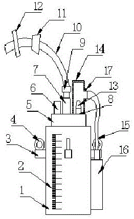
[0014] Such as figure 1 As shown, a negative pressure indicating drainage bottle, which includes a bottle body 1, the front of the bottle body 1 is provided with a measurement scale line 2, and the front middle part of the bottle body 1, the back middle part, the left middle part and the right side The middle part is provided with a mounting base 3, the upper side of the mounting base 3 is provided with a suspension ring 4, the upper side of the bottle body 1 is provided with a bottle cap 5, and the described bottle cap 5 is sequentially provided with vacuum valves from left to right. Indicator 6, drainage port 7 and air suction port 8, said drainage port 7 is connected with a drainage tube 10 through a Luer interface 9, said drainage tube 10 is provided with an anti-reverse valve 11 in the middle, said drainage tube 10 ends A pipe clamp 12 is arranged on the upper part of the pumping port 8, a check valve 13 is provided at the upper end of the pumping port 8, a pumping chambe...

Embodiment 2

[0017] Such as figure 1 As shown, a negative pressure indicating drainage bottle, which includes a bottle body 1, the front of the bottle body 1 is provided with a measurement scale line 2, and the front middle part of the bottle body 1, the back middle part, the left middle part and the right side The middle part is provided with a mounting base 3, the upper side of the mounting base 3 is provided with a suspension ring 4, the upper side of the bottle body 1 is provided with a bottle cap 5, and the described bottle cap 5 is sequentially provided with vacuum valves from left to right. Indicator 6, drainage port 7 and air suction port 8, said drainage port 7 is connected with a drainage tube 10 through a Luer interface 9, said drainage tube 10 is provided with an anti-reverse valve 11 in the middle, said drainage tube 10 ends A pipe clamp 12 is arranged on the upper part of the pumping port 8, a check valve 13 is provided at the upper end of the pumping port 8, a pumping chambe...


PUM


Abstract

The invention relates to a negative-pressure indicating drainage bottle which comprises a bottle body, wherein measurement scale lines are formed on the front surface of the bottle body, mounting bases are respectively arranged in the middle parts of the front surface, the back surface, the left side and the right side of the bottle body, hanging rings are arranged on the upper sides of the mounting bases, a bottle cap is arranged on the upper side surface of the bottle body, a vacuum indicator, a drainage opening and an extraction opening are arranged on and formed in the bottle cap in sequence from left to right, the drainage opening is connected with a drainage tube through a Ruhr connector, a reflux valve is arranged in the middle of the drainage tube, a tube clamp is arranged on the end of the drainage tube, a check valve is arranged on the upper end of the extraction opening, an extraction chamber is arranged outside the extraction opening, a connecting tube is connected to the right end of the extraction chamber, and a minipump is connected to the other end of the connecting tube. The negative-pressure indicating drainage bottle has the advantages of simple structure, safety, accuracy, good use effect and strong practicability.

Description

technical field [0001] The invention belongs to the technical field of medical devices, in particular to a negative pressure drainage bottle, in particular to a negative pressure indicating drainage bottle. Background technique [0002] For patients with common diseases or infectious diseases, the negative pressure drainage devices currently used in clinical practice will produce physiological secretions and secretions from the attracted body organs. The secretions are easy to collect and process, but the secretions are more sticky. Thick, sometimes physiologically semi-solidified drainage, if the drainage device can not well adjust the internal negative pressure drainage pressure and rate, it is likely to cause pipeline blockage after drainage of secretions, causing many complications, which is very serious for doctors and nurses The medical work of personnel has had a certain impact. Contents of the invention [0003] The purpose of the present invention is to overcome ...

Claims


Application Information

Patent Timeline
Patent Type & Authority Applications(China)
IPC IPC(8): A61M1/00
CPCA61M1/0003A61M1/80
Inventor 韩立涛张正男李风光闫钧李伟甲柳小军
Owner HENAN YADU IND
Why Eureka
Try Eureka