

Integrated spiral-flow reaction and separation system and process for sulfur containing gas desulfuration
A cyclone reaction and cyclone separator technology, which is applied in separation methods, dispersed particle separation, chemical instruments and methods, etc., can solve the problems of large initial investment in space-occupied equipment, inconvenient maintenance and increased energy consumption, etc. Achieve the effects of saving space, simplifying structural complexity, and saving energy
- Summary
- Abstract
- Description
- Claims
- Application Information
AI Technical Summary
Problems solved by technology
Method used
Image

Examples
Embodiment 1
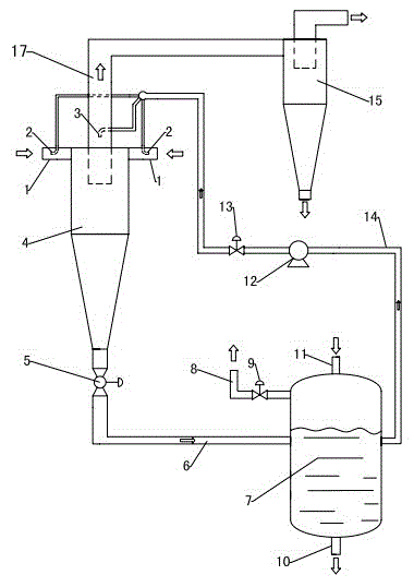
[0037] Refer to attached figure 1 : An integrated cyclone reaction and separation system for sulfur-containing gas desulfurization, comprising a cyclone reactor 4, a bottom flow ratio regulating valve 5, a rich liquid drainage pipeline 6, an amine liquid storage tank 7 and a gas-liquid cyclone separator 15, and the cyclone The lower part of the flow reactor 4 is connected to one side of the amine liquid storage tank 7 through the rich liquid discharge line 6, and the other side of the amine liquid storage tank 7 is connected to the upper liquid inlet end of the swirl reactor 4 through the absorption liquid circulation line 14, and the swirl reaction The upper part of the device 4 is connected to the gas-liquid cyclone separator 15 through an exhaust device.
[0038] The swirling flow reactor 4 comprises a main body and a tangential inlet nozzle 1, the upper part of the main body is provided with a tangential inlet nozzle 1, one or several tangential inlet nozzles 1 are provide...
Embodiment 2
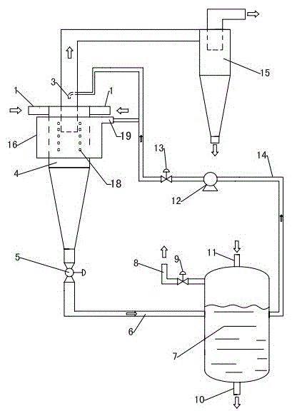
[0050] Refer to attached figure 2 : The outer cylinder body 16 for temporarily storing the absorption liquid is set on the outer side of the upper part of the swirling flow reactor 4 main body, the upper part of the main body is uniformly distributed with liquid inlet holes 18 in a ring, and the upper part of the outer cylinder body 16 is provided with a liquid inlet port 3 tangentially. The end of the absorption liquid circulation pipeline 14 is divided into two lines, and the two lines are respectively connected to the atomizing nozzle 2 inserted into the liquid inlet 3 and the exhaust core pipe 17 . The liquid inlet hole 18 can be a plurality of small circular holes uniformly distributed in a ring. Other settings and working principles are the same as in Embodiment 1.
Embodiment 3
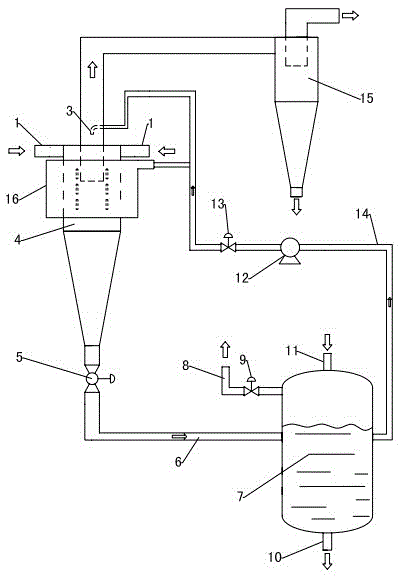
[0052] Refer to attached image 3 : The outer cylinder 16 for temporary storage of the absorption liquid is set outside the upper part of the swirling flow reactor 4 main body, the upper part of the main body is uniformly distributed with liquid inlet holes 18 in a ring, and the upper outer cylinder 17 is provided with a liquid inlet 3 tangentially. The liquid inlet hole 18 can be a plurality of circular uniformly distributed elongated holes. Other settings and working principles are the same as in Embodiment 2.
PUM
 Abstract
Description
Claims
Application Information