Ladle capping device

A ladle and molten iron technology, applied in metal processing equipment, casting molten material containers, casting equipment, etc., can solve problems such as uneven temperature of molten iron, poor working environment for workers, influence of molten iron transportation scheduling, etc., to achieve obvious effects, Save consumption and design simple effect

Inactive Publication Date: 2015-12-02
唐山瑞丰钢铁(集团)有限公司
View PDF5 Cites 3 Cited by
  • Summary
  • Abstract
  • Description
  • Claims
  • Application Information

AI Technical Summary

Problems solved by technology

The loss of heat leads to uneven temperature of the molten iron, and also reduces the life of the lining
Although there is currently a method of adding rice stalks to the ladle for heat preservation, the heat preservation effect of this method is not obvious, and it will cause environmental pollution, the working environment of workers is harsh, and the manufacturing cost of steel enterprises will greatly increase.
[0003] In recent years, iron and steel enterprises have successively begun to study the use of torpedo tank trucks for the transportation of molten iron. Torpedo tank trucks carry a large amount of molten iron and the temperature during transportation is lowered. , this will still produce a lot of iron loss and heat loss
Moreover, the torpedo tank car transportation of molten iron is not suitable for most manufacturers, because the use of torpedo tank cars requires all the ladles to be discarded, and the transportation of molten iron is generally carried out by rail. If torpedo tank cars are used, the railway lines will be re-arranged, resulting in a huge amount of engineering. The scheduling of molten iron transportation also has a serious impact, so most iron and steel enterprises still use ordinary ladles during the transportation of molten iron. The number of molten iron ladles sent per trip is 4 to 6. The quantity is large, and it is difficult to install the ladle cover

Method used


Image

  • Ladle capping device
  • Ladle capping device

Examples


Embodiment Construction

[0023] The present invention will be described in detail below in conjunction with the accompanying drawings and embodiments, the purpose is only to understand the technical solution of the present invention more clearly, and the examples cited are not intended to limit the scope of protection of the present invention.

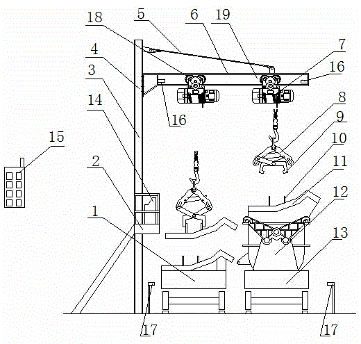
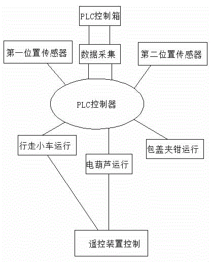
[0024] A ladle capping device, comprising a frame, a lifting device, a ladle cover 11, a trolley 1, a ladle car 13, a ladle cap clamping device and a control system; The ladle cover 11 is connected, and the other end is connected with the frame, and the lifting device can move laterally relative to the frame; and cover removal operation; the traveling trolley 1 and the hot metal charter car 13 run in opposite directions, and run back and forth relative to the frame; the control system includes a PLC control box 14, an operating platform 2 and a remote control device 15.

[0025] In the present embodiment, the hot metal ladle cover clamping device comprises a c...


PUM


Abstract

The invention relates to a ladle capping device and belongs to the technical field of molten iron transportation of iron works. The ladle capping device comprises a rack, a lifting device, a ladle cap, a walking trolley, a ladle vehicle and a ladle cap clamping device, wherein one end of the lifting device is connected with the ladle cap through the ladle cap clamping device, the other end of the lifting device is connected with the rack, and the lifting device can horizontally move relative to the rack; the ladle cap moves up and down and moves leftwards and rightwards relative to the rack through the lifting device and is added or removed; the walking trolley and the ladle vehicle drive in opposite directions and run in the front-back direction of the rack. The ladle capping device is reasonable in structure, simple to operate and capable of reducing heat loss in the transportation process of the molten iron.

Description

technical field [0001] The invention relates to a ladle capping device, which belongs to the technical field of molten iron transportation in ironworks. Background technique [0002] At present, the transportation of molten iron in ironworks basically runs with the ladles open. When the ladle full of molten iron is running open, during the period from the blast furnace taphole of the ironworks to the steelmaking workshop waiting to be poured into the converter, the molten iron ladle is seriously encrusted along the ladle, which will cause part of the molten iron to be dumped during the pouring process. Stay in the bag. Moreover, the empty ladle ladle runs open, the heat dissipation area doubles, and the heat loss is more serious. When receiving molten iron, some ladle linings have turned black, and the retained molten iron solidifies, causing corrosion to the molten iron ladle lining and reducing the temperature of the molten iron ladle. Lining life. The heat loss of the ...

Claims


Application Information

Patent Timeline
IPC IPC(8): B22D41/00
Inventor 齐超群
Owner 唐山瑞丰钢铁(集团)有限公司
Why Eureka
Try Eureka