Dual-shaft positioning link mechanism

A connecting rod mechanism and shaft positioning technology, which is applied in the direction of large fixed members, metal processing machinery parts, metal processing equipment, etc., can solve the problems of low automation, low work efficiency, manual operation, etc., achieve high efficiency, avoid cumbersome and Inefficient, highly automated effects

Inactive Publication Date: 2015-12-02
CHONGQING HANFANG STEEL STRUCTURE
View PDF1 Cites 0 Cited by
  • Summary
  • Abstract
  • Description
  • Claims
  • Application Information

AI Technical Summary

Problems solved by technology

[0004] Chinese patent CN202063671 has the following technical defects: 1. Manual operation is required for lifting and turning steps, and the degree of automation is low
2. The lifting and turning steps need to be carried out step by step, which cannot be completed in the same way, and the work efficiency is low

Method used


Image

  • Dual-shaft positioning link mechanism
  • Dual-shaft positioning link mechanism

Examples


Embodiment Construction

[0019] The present invention will be described in further detail below by means of specific embodiments:

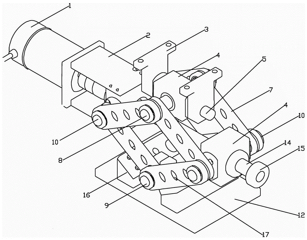
[0020] The reference signs in the drawings of the description include: motor 1, connecting plate 2, lug plate 3, mounting block 4, rotating pin 5, connecting rod 7, positioning shaft 8, fixed shaft 9, rotating shaft 10, platform plate 11, horizontal Bottom plate 12, support mechanism 13, screw rod 14, nut 15, lower limit block 16, connecting hole 17.

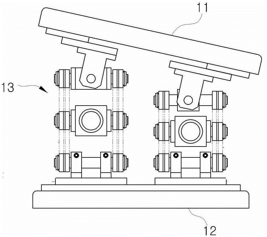
[0021] Such as figure 1 As shown, the biaxial positioning link 7 mechanism in this embodiment includes a platform plate 11 , a horizontal bottom plate 12 and two sets of supporting mechanisms 13 arranged between the platform plate 11 and the horizontal bottom plate 12 .

[0022] Such as figure 2 As shown, each group of supporting mechanisms 13 includes a fixed shaft 9, two rotating shafts 10 and a positioning shaft 8, and the fixed shaft 9 is fixed on the horizontal base plate 12; Two rotating shafts 10 and a connecting...


PUM


Abstract

The invention discloses a link mechanism, and particularly relates to a dual-shaft positioning link mechanism which comprises a platform plate and a lifting mechanism arranged below the platform plate. The lifting mechanism comprises two supporting mechanisms. Each supporting mechanism comprises a fixed shaft, two rotating shafts and a positioning shaft. The positioning shafts of the two supporting mechanisms are both hinged to the platform plate. The fixed shafts of the two supporting mechanisms are fixed to the same horizontal position. The two rotating shafts of each supporting mechanism are connected with the corresponding fixed shaft and the corresponding positioning shaft through connecting rods respectively, a screw is arranged between the two rotating shafts, one rotating shaft is connected with the screw in a threaded mode, the other end of the rotating shaft is fixedly provided with a motor, and an output shaft of the motor is connected with the screw. The technical defects that in the prior art, the automation degree is low and work efficiency is low are overcome, and the dual-shaft positioning link mechanism can be automatically controlled and is high in efficiency.

Description

technical field [0001] The invention relates to a link mechanism, in particular to a biaxial positioning link mechanism. Background technique [0002] A machining platform is a platform for machining mechanical workpieces, and usually includes a platform plate and a support column for supporting the platform plate. [0003] Practical application requires certain height lifting and angle tilting of the platform board according to the different processing requirements of the work. A lifting platform is provided in the prior art, the platform board is screwed to the stud, and then the stud is driven to rotate by a manual wheel, so as to realize the lifting of the platform board; the platform board is also hinged on the upper end of the stud through a hinge , when the platform plate reaches a certain height, adjust the flip angle of the platform plate through the hinges, and then lock the hinges, the lifting and flipping positioning of the platform plate can be realized. [00...

Claims


Application Information

Patent Timeline
Patent Type & Authority Applications(China)
IPC IPC(8): B23Q1/25B23Q1/44
CPCB23Q1/25B23Q1/44
Inventor 李波
Owner CHONGQING HANFANG STEEL STRUCTURE
Why Eureka
Try Eureka