Kinetic-static energy conversion type fresh air system

A fresh air system and conversion technology, applied in railway car body parts, railway vehicle heating/cooling, transportation and packaging, etc., can solve passenger injuries and other problems, achieve the effect of increasing the overall height, ensuring driving safety, and simple structure

Inactive Publication Date: 2015-12-02
UNIV OF JINAN
View PDF6 Cites 1 Cited by
  • Summary
  • Abstract
  • Description
  • Claims
  • Application Information

AI Technical Summary

Problems solved by technology

This train malfunctioned because it could not stop at the station and caused passenger injuries.

Method used


Image

  • Kinetic-static energy conversion type fresh air system
  • Kinetic-static energy conversion type fresh air system
  • Kinetic-static energy conversion type fresh air system

Examples


Embodiment 1

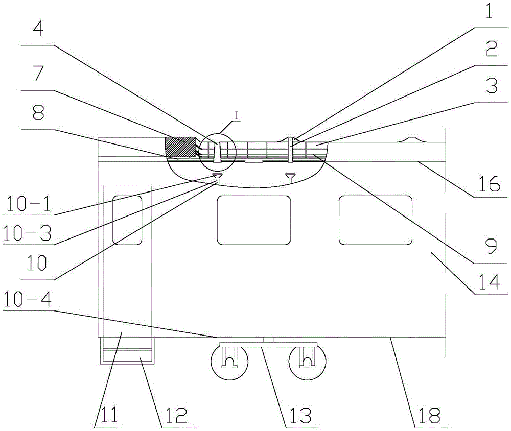
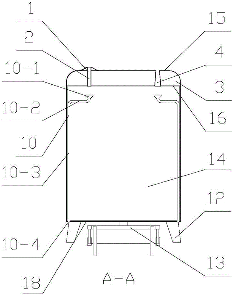
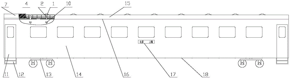
[0061] 1. Dynamic and static energy conversion fresh air system, including: negative pressure air nozzle 1, negative pressure ventilation pipe 2, roof equipment compartment 3, positive pressure ventilation pipe 4, rain drainage assembly 10, compartment 14, roof skin 15, compartment Ceiling 16, compartment floor 18; (Note: the roof skin is the roof shell);

[0062] The positive pressure ventilation pipe 4 includes: the upper nozzle 4-1 of the positive pressure pipe and the lower nozzle 4-2 of the positive pressure pipe; the rain drainage assembly 10 includes: a rainwater funnel 10-1, a rain drainage horizontal pipe 10-2, Pipe 10-3, rain discharge nozzle 10-4;

[0063] It is characterized by:

[0064] Negative pressure ventilation pipe 2 is a cylindrical pipe; Positive pressure ventilation pipe 4 is a tube in the shape of a trumpet with upper nozzle 4-1 on the positive pressure pipe and a lower nozzle 4-2 on the positive pressure pipe; Upper nozzle 4 on the positive pressure pi...

Embodiment 2

[0087] 1. Dynamic and static energy conversion fresh air system, including: negative pressure air nozzle 1, negative pressure ventilation pipe 2, roof equipment compartment 3, positive pressure ventilation pipe 4, rain drainage assembly 10, compartment 14, roof skin 15, compartment Ceiling 16, compartment floor 18; (Note: the roof skin is the roof shell);

[0088] The positive pressure ventilation pipe 4 includes: the upper nozzle 4-1 of the positive pressure pipe and the lower nozzle 4-2 of the positive pressure pipe; the rain drainage assembly 10 includes: a rainwater funnel 10-1, a rain drainage horizontal pipe 10-2, Pipe 10-3, rain discharge nozzle 10-4;

[0089] It is characterized by:

[0090] Negative pressure ventilation pipe 2 is a cylindrical pipe; Positive pressure ventilation pipe 4 is a tube in the shape of a trumpet with upper nozzle 4-1 on the positive pressure pipe and a lower nozzle 4-2 on the positive pressure pipe; Upper nozzle 4 on the positive pressure pi...


PUM


Abstract

The invention relates to a kinetic-static energy conversion type fresh air system, which relates to the field of ventilation of a passenger train. The kinetic-static energy conversion type fresh air system is characterized in that a negative pressure ventilation pipe is a straight pipe; a positive pressure ventilation pipe is a trumpet-shaped pipe; the top of a negative pressure air tap is a convex streamline-shaped arc surface; the top end of the negative pressure air tap is connected with a roof skin; the negative pressure ventilation pipe penetrates into a carriage through the lower part of a roof equipment cabin and a connecting pipe port of a carriage ceiling; the top end of the positive pressure ventilation pipe is connected with the roof skin; the lower end of the positive pressure ventilation pipe is positioned in the carriage; the lower end of a rainwater funnel is connected with a rainwater draining cross pipe; the rainwater draining cross pipe is connected with a rainwater draining vertical pipe; the rainwater draining vertical pipe leans close to the inner wall of the carriage; the bottom end of the rainwater draining vertical pipe is connected with a rainwater draining pipe port; the rainwater draining vertical pipe penetrates through a carriage bottom plate; the rainwater draining pipe port is formed in the exterior bottom of the carriage; the rainwater funnel is right against the downside of the negative pressure ventilation pipe; and the rainwater funnel is arranged right under the positive pressure ventilation pipe. The kinetic-static energy conversion type fresh air system provided by the invention is superior to the prior art in ventilation effect and has the advantages of simple structure and low cost.

Description

technical field [0001] The dynamic and static energy conversion type fresh air system relates to the field of passenger car ventilation. Background technique [0002] my country's railway network spreads all over the country, and railway passenger transport is still the mainstream means of transportation. For a long time, the passenger flow of railway transportation has been large, especially during the spring and summer travel seasons, ordinary seats are often full or overcrowded, and the air quality will decline when crowded passengers are in narrow compartments. In order to make use of natural wind to adjust fresh air into the compartment, the Chinese patent CN202006797U patent of the prior art, due to the structural form of its fresh air pipe 1 and exhaust pipe 2, provides 10 bendings in both directions, and the fresh air pipe 1 and exhaust pipe The pressure difference between 2 is almost exhausted through the local resistance loss of 10 bends, and the ventilation effec...

Claims


Application Information

Patent Timeline
Patent Type & Authority Applications(China)
IPC IPC(8): B61D27/00
Inventor 马晶戚玉华许崇娟
Owner UNIV OF JINAN
Why Eureka
Try Eureka