A leading edge flap control method

A leading edge flap and control method technology, applied in the field of aircraft leading edge flap control and leading edge flap control, can solve the problems of large transients of the aircraft, affecting the flight quality, increasing the pilot's control load, etc., so as to improve the flight quality , Improve the effect of high angle of attack stall characteristics requirements

Active Publication Date: 2017-05-17
JIANGXI HONGDU AVIATION IND GRP
View PDF9 Cites 0 Cited by
  • Summary
  • Abstract
  • Description
  • Claims
  • Application Information

AI Technical Summary

Problems solved by technology

Although these two control methods can achieve the effect of increasing the lift and improving the stall characteristics at high angles of attack, they also have shortcomings: one is to manually control the leading edge flaps, which increases the pilot's control load; , it is easy to cause the aircraft to have a large transient state, which will affect the flight quality

Method used


Image

  • A leading edge flap control method
  • A leading edge flap control method

Examples


Embodiment Construction

[0018] In order to make the technical means, creative features, goals and effects achieved by the present invention easy to understand, the present invention will be further described below in conjunction with specific illustrations.

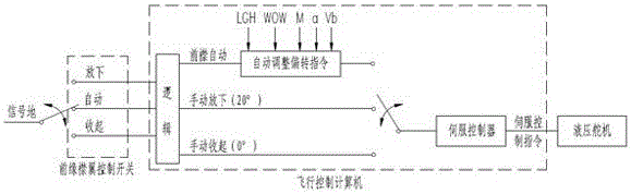
[0019] A leading-edge flap control method such as figure 1 As shown, the aircraft cockpit is provided with a leading edge flap control switch, the leading edge flap control switch is connected with the flight control computer, and the flight control computer is connected with the hydraulic steering gear; at the same time, the flight control computer is based on the position of the leading edge flap control switch and the The leading-edge flap controls the deflection law to generate digital control commands, and the servo controller installed in the flight control computer converts the digital control commands and hydraulic steering gear position feedback signals through servo amplification and signal conversion to generate hydraulic steering gear...


PUM


Abstract

The invention relates to a leading-edge flap control method. A leading-edge flap control switch is arranged in an aircraft cockpit, and the leading-edge flap control switch is connected with a flight control computer which is connected with a hydraulic steering gear; besides, the flight control computer generates digital control commands according to the position of the leading-edge flap control switch and the deflection rules for leading-edge flap control, and a servo controller arranged in the flight control computer processes the digital control commands and position feedback signals of the hydraulic steering gear through servo amplification and signal conversion, and generates servo commands for the hydraulic steering gear, in order to control the hydraulic steering gear to push rudder surface deflection of leading-edge flaps; manual control or automatic control of the leading-edge flaps can be quickly realized, the leading-edge flap control method is suitable for the control of the leading-edge flaps of fixed-wing aircrafts, not only meets the demands for increasing lifting force during an aircraft takeoff stage and an aircraft landing stage as well as improving the stallout characteristics at large angle of attack, but also reduces the operating load of pilots and reduces retracting and launching transients of the leading-edge flaps, so that the flying quality is effectively improved.

Description

technical field [0001] The invention relates to the technical field of aircraft leading edge flap control, in particular to a leading edge flap control method. Background technique [0002] The leading-edge flap is a section or several sections of long and narrow winglets installed on the leading edge of the wing. It relies on increasing the camber of the airfoil to obtain a lift increase device; the main function of the leading-edge flap is: a delay of the wing Separation of the airflow on the top to increase the critical angle of attack of the aircraft, so that the aircraft will stall at a larger angle of attack; two increase the lift coefficient of the wing. [0003] At present, domestic and foreign aircraft mainly use automatic leading-edge flaps, that is, the leading-edge flaps are connected to the wings through the steering gear, so as to automatically open and close according to the change of the angle of attack; In the closed state, when the angle of attack increase...

Claims


Application Information

Patent Timeline
Patent Type & Authority Patents(China)
IPC IPC(8): B64C13/40B64C13/16
Inventor 杨杰红谢慧慈刘欣陈林张坤崔彦勇项国辉万明张羽白涂良辉周恒杨昆
Owner JIANGXI HONGDU AVIATION IND GRP
Why Eureka
Try Eureka