
Tool clamp capable of adjusting overhang amount of tool in a large range

A technology for adjusting tools and tool clips, which is applied in the direction of manufacturing tools, clamping, and metal processing equipment, etc., which can solve the problems of tool clip manufacturing troubles, increased quality, and difficulties, so as to increase the adjustable range and increase the insertion space , the effect of reducing labor intensity

Active Publication Date: 2012-06-27
ZHUZHOU CEMENTED CARBIDE CUTTING TOOLS CO LTD
View PDF6 Cites 0 Cited by
  • Summary
  • Abstract
  • Description
  • Claims
  • Application Information

AI Technical Summary

Problems solved by technology

If the overhang is longer, the rigidity of the workpiece processing part will decrease, so it will be difficult to cut, and it will be difficult to maintain the machining accuracy and the roughness of the machined surface
In this case, in order to make the amount of overhang the same, it is necessary to use a tool holder with a large tool holder depth, which leads to an increase in the overall length and mass of the tool holder, and it is necessary to prepare various types Tool holders to meet the needs of production
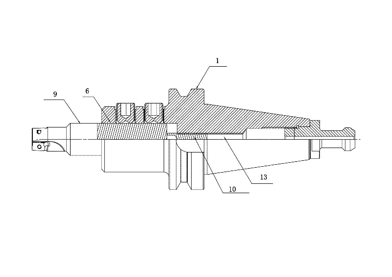
[0003] A tool clip with adjustable overhang of the prior art such as figure 1 As shown, there is an adjustment screw installation hole 13 behind the tool installation hole 6 of the tool holder body 1, and the overhang of the workpiece can be adjusted by screwing in and out of the adjustment screw 10. Although this tool holder can meet a certain range of overhang of the workpiece amount, but the adjustable range is relatively small, only shorter workpieces 9 can be installed, and only tool holders can be replaced for relatively long workpieces 9; The inside of 13 has threads, and the production of the tool holder is troublesome; in addition, the installation of the adjustment screw 10 is also troublesome.

Method used


Image

  • Tool clamp capable of adjusting overhang amount of tool in a large range
  • Tool clamp capable of adjusting overhang amount of tool in a large range
  • Tool clamp capable of adjusting overhang amount of tool in a large range

Examples


Embodiment Construction

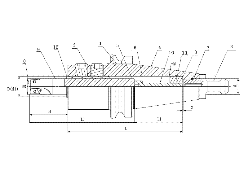
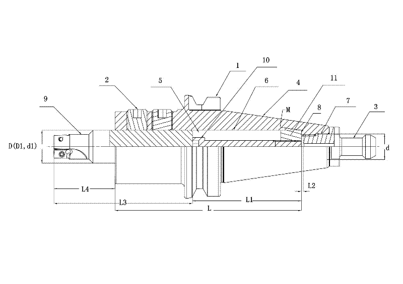
[0020] Figure 2 to Figure 4 It shows a tool clip embodiment of the present invention that can adjust the overhang of the tool in a large range. The tool clip includes a tool clip body 1, a workpiece clamping mechanism 2 and a pull screw 3. The tool clip body 1 is provided with a machine tool. The taper shank part 4 that matches the hole and a cavity 5 that runs through the entire tool holder body 1. The cavity 5 is composed of a tool mounting hole 6 and a standard pull screw hole 7. The diameter D of the tool mounting hole 6 is larger than the standard pull screw hole 7 In this embodiment, D=32mm, d=21mm, the tool installation hole 6 and the standard traction screw hole 7 are connected to form a connecting surface 8, and the tool installation hole 6 is equipped with a detachable adjustment screw 10 and an adjustment nut 11 One end of the adjustment nut 11 is offset against the connection surface 8, and the other end is connected with the adjustment screw 10. The cavity 5 that...


PUM


Abstract

The invention discloses a tool clamp capable of adjusting the overhang amount of a tool in a large range, which comprises a tool clamp body, a work piece clamping mechanism and a traction screw. The tool clamp body is provided with a taper shank part matched with a machine tool mounting hole and a die cavity penetrating through the whole tool clamp body; the die cavity comprises a tool mounting hole and a standard traction screw hole; the bore diameter D of the tool mounting hole is larger than the bore diameter d of the standard traction screw hole; the tool mounting hole and the standard traction screw hole are connected to form a connecting surface; a demountable adjusting screw and an adjusting nut are installed in the tool mounting hole; one end of the adjusting nut is propped against the connecting surface; and the other end of the adjusting nut is connected with the adjusting screw. The tool clamp has the advantages of high dismounting speed, light weight, high re-positioning accuracy, high machining efficiency and wide clamping scope.

Description

technical field [0001] The invention relates to a tool holder for machining, in particular to a tool holder capable of adjusting the overhang of a tool in a large range. Background technique [0002] In the metal cutting industry, the installation accuracy of cutting tools will have a great impact on the processing efficiency and the surface quality of processed products. Improving the installation accuracy of cutting tools is the goal that the entire manufacturing industry is constantly pursuing. To make the installation accuracy of the cutting tool reach a higher level, it is necessary to have a high-precision tool holder and a high-precision tool to cooperate, and to make the overhang of the tool as small as possible, so that the cutting edge of the tool is as close as possible to the end face of the spindle. . At present, when using existing tool holders to mount workpieces with different overall lengths, since the workpieces enter the tool holder at the same depth, the...

Claims


Application Information

Patent Timeline
Patent Type & Authority Applications(China)
IPC IPC(8): B23Q3/12
Inventor 李巍巍宋步光杨德图项兴东
Owner ZHUZHOU CEMENTED CARBIDE CUTTING TOOLS CO LTD
Learn More