Plastic bag packer

A packaging machine, plastic bag technology, applied in packaging, transportation packaging, paper product packaging and other directions, can solve the problems of packaging bag adhesion, complex movements, fast packaging speed of plastic bag packaging machines, etc., to ensure length accuracy and stable work. Reliable, stable and reliable bag making effect

Inactive Publication Date: 2015-12-02
王秀来
View PDF12 Cites 30 Cited by
  • Summary
  • Abstract
  • Description
  • Claims
  • Application Information

AI Technical Summary

Problems solved by technology

But the problem caused by this is: the suction plate swings above the bag storage tray. When absorbing the top packaging bag in the storage bag tray, due to electrostatic adsorption, repeated bag extrusion, etc., the gap between the packaging bags will be caused. Adhesion between them, sometimes two or more bags will be sucked up at one time
The problem is that, firstly, it can be clearly seen from the drawings disclosed in comparative documents 1, 2, and 3 that the left side of the bag opening device of the plastic bag packaging machine is provided with a lifting pallet and a supporting plate device, and a bag making device cannot be installed; There is an output device on the upper right side, and the place where the bag making device can be installed is only in the narrow L-shaped space below the output device
However, the bag-making device of the prior art is complex in structure, bulky, and high in cost, so it is difficult to match it.
Second, the packaging speed of the plastic bag packaging machine is fast and the action is complicated
Third, the packaging bag made by the bag making device is light in weight and easy to drift. It is difficult to fix the packaging bag immediately after ou

Method used


Image

  • Plastic bag packer
  • Plastic bag packer
  • Plastic bag packer

Examples


Embodiment 1

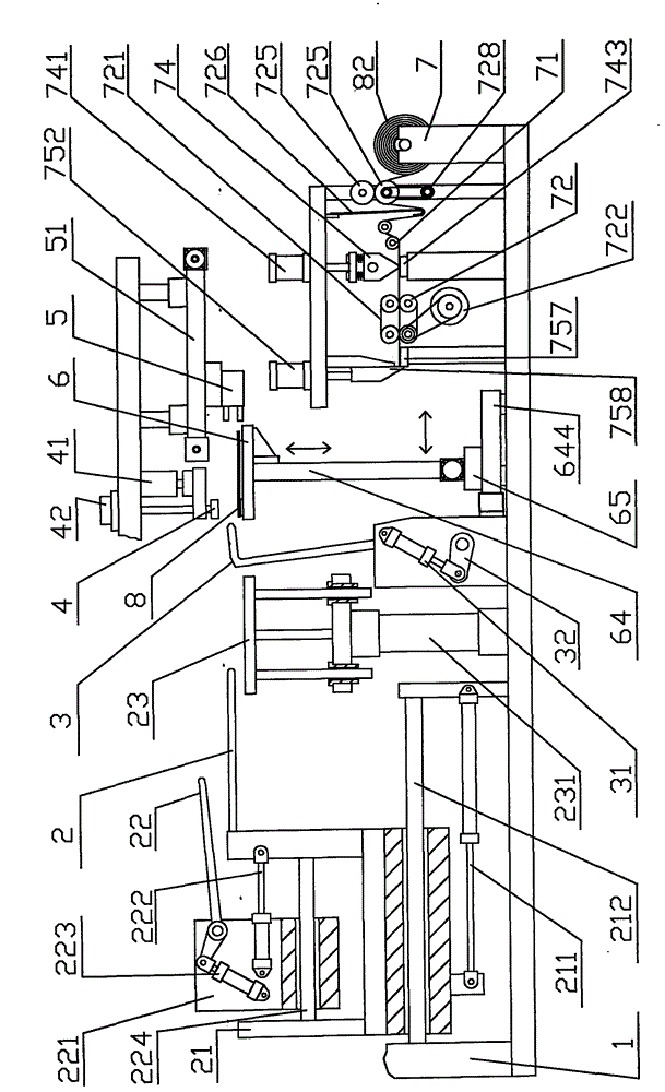
[0045] Example 1: Please refer to figure 1 , figure 2 , image 3 . On the lower frame 1 corresponding to the suction cup 4, the electric slide table 644 is installed front and rear, on the slide table 65 of the electric slide table, two linear modules 64 are erected left and right, and the two synchronous wheels below the two modules 64 are connected to the transmission shaft. 643, one end of the drive shaft 643 is connected to the module motor 642, a bracket 611 is installed on the two slide blocks 641 of the two modules 64, and the storage bag tray 6 is installed on the bracket 611; on the front side of the storage bag tray 6 Suction nozzle 61 is installed in the position corresponding up and down with lifting suction cup 4 in the middle, and suction nozzle 61 communicates with suction fan 62 with pipeline 63, as Figure 8 shown. Described electric sliding table 644 and linear module 64 belong to known technology, just can buy on the market. The above embodiment is the...

Embodiment 2

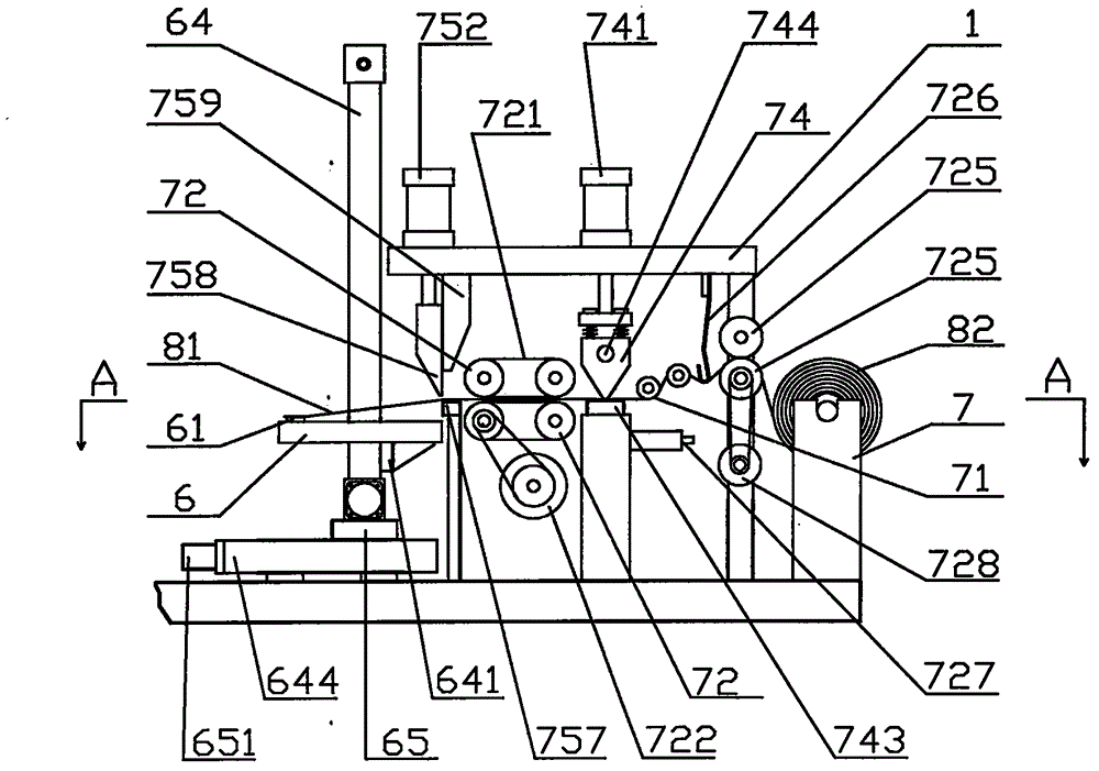
[0054] Embodiment 2: The main difference between Embodiment 2 and Embodiment 1 is that: the front and rear ends of the bag storage tray 6 are provided with suction nozzles 61; Clamping manipulator etc. constitute, omitted the pre-discharging device of embodiment 1; Cutting mechanism is made of cutting seat 751, rodless cylinder 753, blade 75, cutting backing plate 755, concave pressing plate 756 etc.

[0055] Such as Figure 12 Shown: a pressure roller 736 is installed in front of the guide roller 71, the two ends of the pressure roller 736 are respectively equipped with rocking arms, the other ends of the two rocking arms are hinged on the frame, and the guide rollers are installed on the frame below the pressure roller 736. Rod cylinder 735, lift platform 734 is installed on the guide rod cylinder 735, and pressure roller 736 also moves up and down thereupon when rising or descending. Two linear modules 731 are installed front and rear on both sides of the lower frame corre...

Embodiment 3

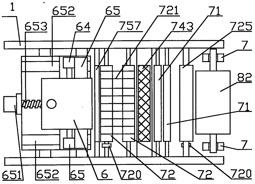
[0057]Embodiment 3: The difference between Embodiment 3 and Embodiment 1 is that the bag-feeding mechanism is only a set of upright sides of the lower frame corresponding to the lifting suction cup 4 up and down, and the electric slide table is omitted; A bag-making track 711 is installed between the racks, and the bag-making device is slid on the bag-making track 711 through a slider 714. A screw pair 712 is installed between the bag-making device and the frame 1, and the packaging is adjusted by turning the hand wheel 713. The optimum opening position of bag and the position of suction cup 61.

[0058] Such as Figure 16 , Figure 17 As shown: the four output rubber rollers 72 in the output mechanism of the bag making device are changed to two, and the two output rubber rollers 72 are elastically connected on the rubber roller track up and down, and are in multiple annular grooves of the two output rubber rollers 72 Conveying air pipes 729 are installed respectively, and t...


PUM


Abstract

The invention discloses a plastic bag packer used for packing low-cost plastic bags produced by a bag making machine. The plastic bag packer mainly comprises a rack, a feeding device, a support plate swinging device and a lifting sucking disc device, and is characterized by further comprising a bag conveying device and a bag making device; the bag making device is characterized in that an output mechanism is used for inputting package films on film rolls to the operation position of a thermal sealing mechanism and the operation position of a cutting mechanism, then the package films are thermally sealed and cut to form package bags, the package bags are output to a bag storage disc of the bag conveying device; the bag storage disc is used for conveying the package bags to a predetermined operation position of the packer along with a bag-conveying operation mechanism; a suction disc is arranged on the bag storage disc, is used for fixing the bottom layers of open ends of the package bags, and cooperates with the lifting sucking disc to open the openings of the bags. The plastic bag packer has the advantages that the structure is simple and compact, the bags are fed and conveyed stably and reliably in sequence, the technical problem that the bags are taken unstably in sequence of the plastic bag packer in the prior art is solved, the plastic bag packer also has a function of automatically making the bags, and the package cost is saved.

Description

technical field [0001] The invention relates to a packaging machine. Specifically, it is a plastic bag packaging machine that wraps plastic bags with packaging bags. Background technique [0002] The utility model relates to a plastic bag packing machine, which is used for packing the cost plastic bags produced by the bag making machine into the packing bags, so as to facilitate storage, sale and use. Application publication number CN103935567A, published on July 23, 2014, discloses a plastic bag folding and packaging machine (hereinafter referred to as reference document 1), which mainly includes: a folding and loading device, an opening device, and a clamping and output device. Application publication number CN104003027A, published on August 27, 2014, discloses an automatic bagging device for plastic bags (hereinafter referred to as reference document 2). It mainly includes bagging device, bag clamping device, bag supporting device, lifting pallet, bag lifting tray and l...

Claims


Application Information

Patent Timeline
IPC IPC(8): B65B43/04B65B43/18B65B43/30B65B25/14B65B51/26
CPCB65B43/04B65B25/14B65B43/18B65B43/30B65B51/26
Inventor 王秀来
Owner 王秀来
Why Eureka
Try Eureka