Particle material uniform paving apparatus for pneumatic conveying

A technology for pneumatic conveying and granular materials, which is applied in the direction of conveying bulk materials, conveyors, transportation and packaging, etc. It can solve the problems of reduced efficiency, economic loss, large power demand, etc., and achieve the effect of simple structure and avoiding damage

Active Publication Date: 2015-12-02
NANJING AGRI MECHANIZATION INST MIN OF AGRI
View PDF5 Cites 6 Cited by
  • Summary
  • Abstract
  • Description
  • Claims
  • Application Information

AI Technical Summary

Problems solved by technology

Pneumatic conveying is used to transport materials into the silo. Since the materials move along the direction of air flow when blowing out of the pipeline, the materials tend to be concentrated in the same area of ​​the silo. Over time, the phenomenon of material accumulation and uplift is formed, and the volume of the silo cannot be fully utilized. , resulting in reduced efficiency
[0003] Existing devices for uniform spreading of granular materials generally adopt structural forms such as spiral push. This type of device has three disadvantages: first, it has a large demand for power, which is likely to cause a series of problems in power configuration and manufacturing cost; second, it is often It can only disperse the material in one direction, and cannot fully utilize the volume of the silo; third, there is a squeezing effect on the material, which may cause the material to be broken and cause economic losses.

Method used


Image

  • Particle material uniform paving apparatus for pneumatic conveying
  • Particle material uniform paving apparatus for pneumatic conveying
  • Particle material uniform paving apparatus for pneumatic conveying

Examples


Embodiment 1

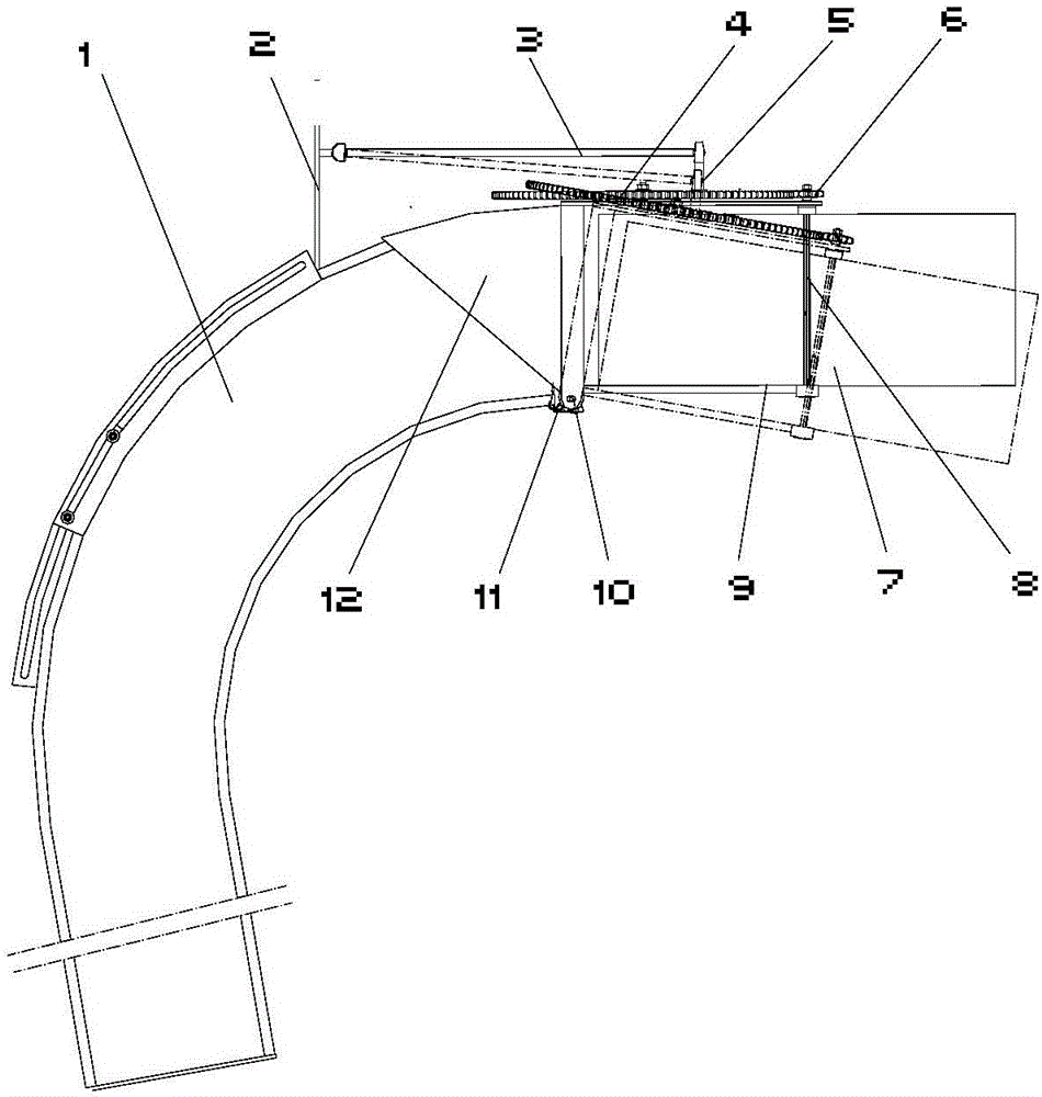
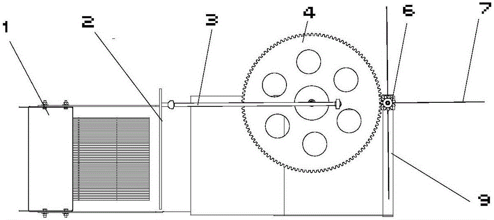
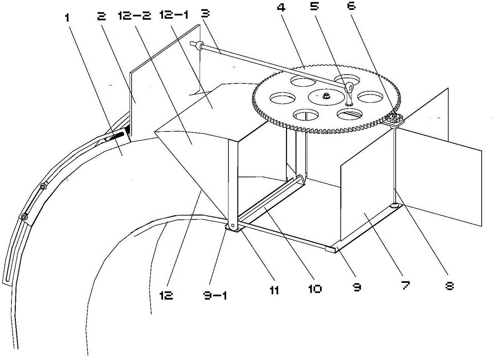
[0019] The structure of the device for uniform spreading of granular materials for pneumatic conveying in this embodiment is as follows: figure 1 , 2 , 3, including a horizontal mounting support 11 fixed on the lower edge of the arc pneumatic conveying end pipeline 1 outlet, the mounting support 11 supports a horizontal hinged shaft 10 perpendicular to the outlet airflow direction, and the hinged support frame is mounted on the hinged shaft 10 9 hinged support sides 9-1 of the rectangular bottom frame. A vertical blade rotating shaft 8 is installed on the opposite side corner of the hinge support limit 9-1 of the rectangular frame, and the blade rotating shaft 8 radially extends out four blades 7 evenly distributed in the circumferential direction. The coaxial pinion 6 is equipped with on the top of the blade rotating shaft 8, and the pinion 6 meshes with the large gear 4 hinged on one side of the support frame 9. The large gear 4 is hinged to one end of the connecting rod 3...


PUM


Abstract

A particle material uniform paving apparatus for pneumatic conveying, belongs to the material conveying mechanical technical field. The apparatus comprises a horizontal installation bearer, an installation bearer support and a horizontal articulated shaft vertical to the outlet air-flow direction; a hinge edge that supports a rectangular bottom frame of the framework is hinged on the articulated shaft; a vertical blade rotating shaft is equipped with at one corner of the opposite edge of the hinge edge of the rectangle frame; the blade rotating shaft extends out of the blades distributed circumferential uniformly in radial direction; a coaxial pinion is installed on the top of the blade rotating shaft; the pinion and a bull gear hinged at one side of the support framework are engaged; the bull gear is hinged to one end of a connecting rod through a connecting rod bearer with a ball hinge; and the other end of the connecting rod is hinged to a sidewall plate fixed on the end pipeline through a spherical hinge head. The pneumatic is used directly as the power and no additional power facility is needed, therefore the structure is simple; vertical and transversal combination can be realized instead of shattering the material in a single direction; the bunker volume can be fully utilized; no extruding effect is applied to the material; and damage to the material is avoided.

Description

technical field [0001] The invention relates to a material spreading device, in particular to a device for evenly spreading granular materials for pneumatic conveying, which belongs to the technical field of material conveying machinery. Background technique [0002] Pneumatic conveying is an application method of fluidization technology that uses the energy of airflow to transport granular materials along the direction of airflow in a closed pipeline. It is widely used in agriculture, foundry, chemical, pharmaceutical and other industries. Pneumatic conveying is used to transport materials into the silo. Since the materials move along the direction of air flow when blowing out of the pipe, the materials tend to be concentrated in the same area of ​​the silo. Over time, the phenomenon of material accumulation and uplift is formed, and the volume of the silo cannot be fully utilized. , resulting in reduced efficiency. [0003] Existing devices for uniform spreading of granul...

Claims


Application Information

Patent Timeline
Patent Type & Authority Applications(China)
IPC IPC(8): B65G53/04B65G53/40B65G69/04
Inventor 胡志超徐弘博曹明珠王申莹于昭洋吴峰顾峰伟陈有庆王公仆
Owner NANJING AGRI MECHANIZATION INST MIN OF AGRI
Why Eureka
Try Eureka