Bearing housing of an exhaust-gas turbocharger

A technology for bearing housings and exhaust turbines, applied in the direction of machines/engines, mechanical equipment, engine components, etc., can solve problems such as inconvenient, production geometry, and cumbersome design of bearing inserts, so as to reduce costs and reduce splash losses Effect

Inactive Publication Date: 2015-12-02
BORGWARNER INC
View PDF7 Cites 0 Cited by
  • Summary
  • Abstract
  • Description
  • Claims
  • Application Information

AI Technical Summary

Problems solved by technology

Even though a simplification of construction and production is attempted by said arrangement, the design of the bearing insert with the oil chamber is cumbersome since it results in a relatively complex geometry that cannot easily be produced by casting

Method used


Image

  • Bearing housing of an exhaust-gas turbocharger
  • Bearing housing of an exhaust-gas turbocharger
  • Bearing housing of an exhaust-gas turbocharger

Examples


Embodiment Construction

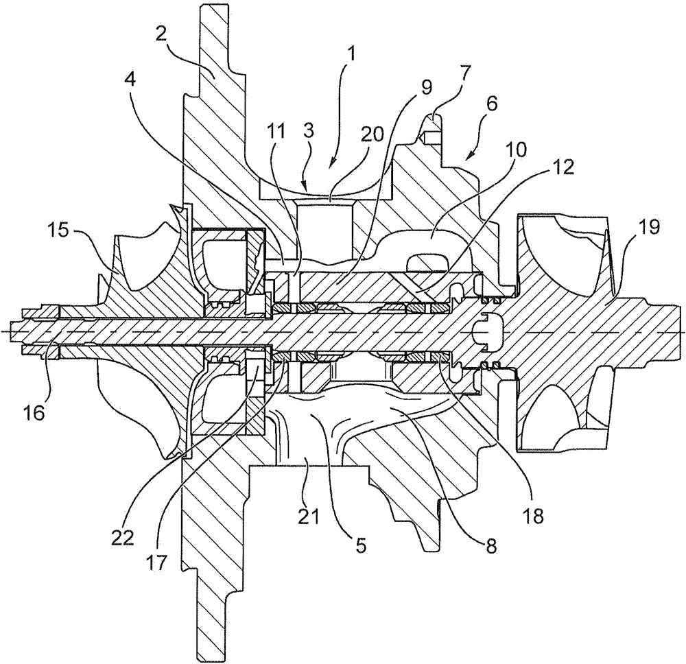
[0020] figure 1 An exhaust-gas turbocharger block set is shown, which has a bearing housing 1 according to the invention. The body pack also comprises a shaft 16, on one side of which the compressor wheel 15 is mounted and the turbine wheel 19 is mounted on the other side of the shaft, so as to form a rotor. The shaft 16 is mounted in the bearing housing 1 via a compressor-side bearing arrangement 17 and a turbine-side bearing arrangement 18 together with an axial bearing 22 . If a compressor housing and a turbine housing (they are in figure 1 not shown in ) is added to the body group, which creates an exhaust-gas turbocharger, so that the invention can also be described as an exhaust-gas turbocharger with a bearing housing 1 , the bearing housing will be described in detail below.

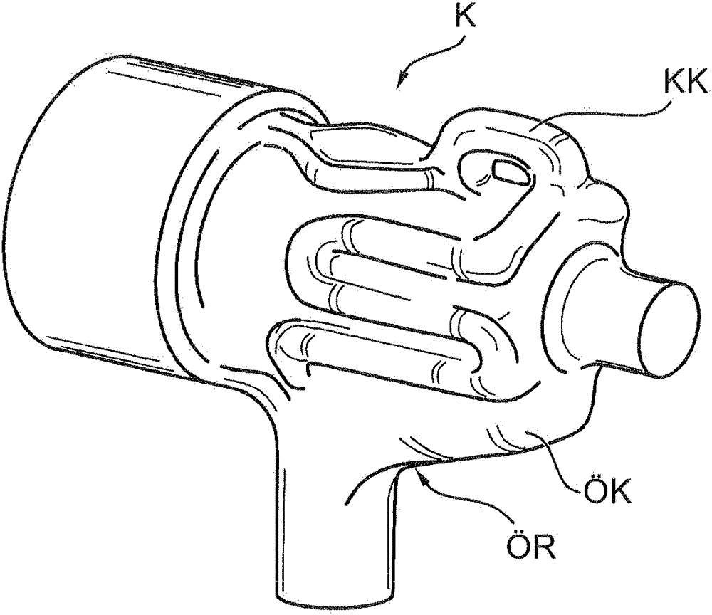
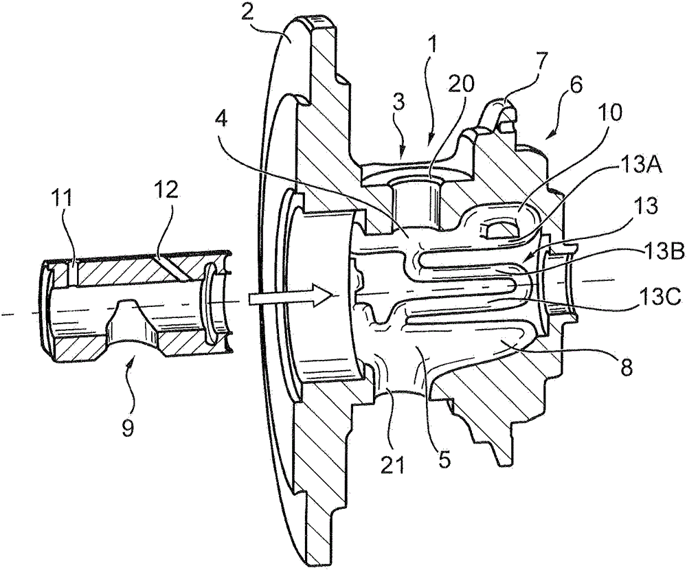
[0021] figure 2 The bearing housing 1 according to the invention is shown before a bearing sleeve 9 is inserted. The bearing housing 1 comprises: a compressor side housing flange 2; a centra...


PUM


Abstract

A bearing housing (1) of an exhaust-gas turbocharger, having a compressor-side housing flange (2), a central housing section (3) which is integrally connected to the housing flange (2) and in which is arranged a first partial section (4) of an oil chamber (5) which has an oil inlet (20) and an oil outlet (21), and a turbine-side housing section (6) which has a turbine-side housing flange (7) and in which is arranged a second partial section (8) of the oil chamber (5). The central and turbine-side housing sections (3, 6) are provided with an oil cooling duct (13; 13′).

Description

[0001] This application is a divisional application of a Chinese patent application with the application number 201180036879.X, the application date being August 19, 2011, and the title "Bearing Housing for Exhaust Turbocharger". technical field [0002] The invention relates to a bearing housing for an exhaust-gas turbocharger according to the preamble of claim 1 . Background technique [0003] A bearing housing of the type mentioned is known from DE 43 30 380 A1. The known bearing housing is divided into a bearing insert and a bearing disc which at least partially surrounds the bearing insert. Here, an oil chamber for cooling the bearings in the bearing housing is formed in the bearing insert, which is a cast part. Even though a simplification of construction and production is attempted by the arrangement described, the design of the bearing insert with the oil chamber is cumbersome since it results in a relatively complex geometry that cannot easily be produced by castin...

Claims


Application Information

Patent Timeline
Patent Type & Authority Applications(China)
IPC IPC(8): F01D25/16F01D25/18F01D25/24
CPCF01D25/16F01D25/162F01D25/183F01D25/24F05D2220/40F02B39/00
Inventor J.霍恩巴赫O.舒明
Owner BORGWARNER INC
Why Eureka
Try Eureka